Okay, let’s talk about this thing called the ‘body effect’ in MOSFETs. I ran into it myself a while back and figured I’d share what I found messing around on my workbench.
Getting Started: Why Bother?
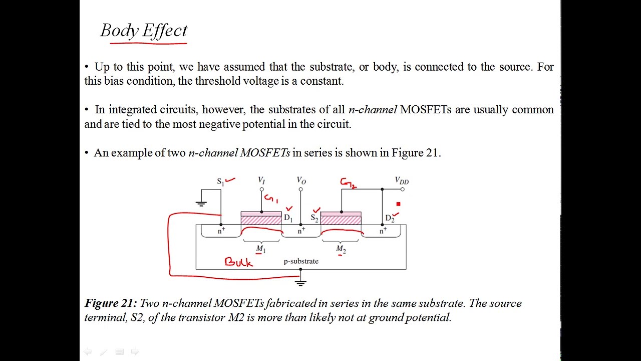
So, I was working on a little project, stacking a couple of NMOS transistors. You know, one on top of the other. I expected them to behave pretty much the same, especially their turn-on voltage, the Vgs threshold. But nope. The top one seemed harder to turn on than the bottom one. That got me thinking. I remembered reading something about the ‘body’ or ‘substrate’ connection messing with things, so I decided to dig into it.
My Simple Setup
Didn’t do anything fancy. I grabbed a standard N-channel MOSFET, the kind you find everywhere. Hooked up my bench power supplies and a couple of multimeters. Here’s basically what I did:
- Connected the Drain and Gate terminals together. This is a common trick to measure the threshold voltage easily.
- Used one power supply for the Drain-Source voltage (Vds). Since Drain and Gate were tied, this also set the Gate-Source voltage (Vgs).
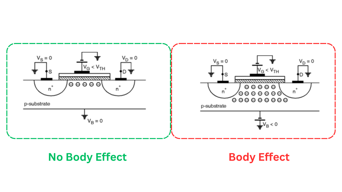
- Used a second power supply specifically for the Body-Source voltage (Vbs). This was the key part. Normally, for a simple NMOS switch, you just tie the Body (or Substrate) to the Source, making Vbs zero.
- Had a multimeter measuring the voltage (Vgs = Vds) and another one set up to measure the tiny drain current (Ids).
Running the Test
First, I did the standard thing: connected the Body to the Source (Vbs = 0V). Then, I slowly cranked up the Vgs (which was also Vds) until I saw a very small, consistent current start to flow through the Drain. Let’s say, maybe 1 microamp or something small like that. Noted down the Vgs value. That’s my baseline threshold voltage, Vt0.
Then came the interesting part. I kept everything else the same, but I started applying a negative voltage between the Body and the Source using that second power supply. So, Vbs became -1V, then -2V, then -3V.
For each different negative Vbs value, I repeated the process: slowly increase Vgs (and Vds) until I hit that same small target Drain current (1 microamp). And I wrote down the Vgs needed each time.
What I Found Out
Well, blow me down, it actually worked like the textbooks said, but seeing it happen is different.
As I made Vbs more negative (meaning the Body was at a lower potential than the Source), I needed a higher Gate-Source voltage (Vgs) to get that same tiny current flowing. The turn-on voltage, the threshold voltage (Vt), clearly increased!
- With Vbs = 0V, maybe Vt was around, say, 1.5V (just an example number).
- With Vbs = -1V, Vt climbed up to maybe 1.7V.
- With Vbs = -3V, Vt went up even more, maybe like 2.1V.
It wasn’t a massive change for each volt, but it was definitely there and measurable. The more reverse bias I put on that Body-Source junction, the harder it was to turn the MOSFET on.
So What? Practical Stuff
This whole exercise made it click why that top transistor in my stack was acting differently. Its Source wasn’t connected to the main ground or the lowest voltage like the bottom one. Its Source was connected to the Drain of the bottom transistor, which was at some voltage above ground when turned on. But its Body (like most integrated transistors on a chip) was probably still tied to the main ground (the lowest potential).
So, the top transistor automatically had a negative Vbs relative to its own Source terminal! That negative Vbs increased its threshold voltage, exactly like I saw in my little test. It wasn’t broken; it was just the body effect doing its thing.

It made me realize you gotta watch out for this whenever a MOSFET’s source isn’t tied directly to its body connection, especially in integrated circuits where many transistors share the same body (substrate). It affects performance, switching speed, all sorts of things. Just something practical I learned by poking around.