Alright, so today I wanted to share a bit about something that tripped me up more than once when I was getting deeper into electronics: the P-channel MOSFET symbol. It sounds basic, and it is, but man, when you’re staring at a schematic and things aren’t working, sometimes it’s the simplest stuff that gets you.
I remember this one project, years ago. I was trying to control a small motor, switching the high side, you know, cutting off the positive supply to it. I thought, “Easy peasy, grab a MOSFET.” I had a bunch of them lying around. I vaguely recalled needing a P-channel for high-side switching, but when I looked at the symbol on the diagram I was sketching out, I got a bit muddled.
My initial confusion went something like this:
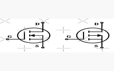
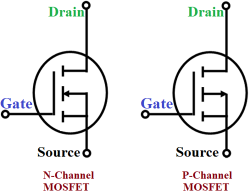
- I’d see the three terminals: Gate, Drain, Source. Okay, standard.
- Then there’s that arrow. That darn arrow.
I kept mixing it up with the N-channel symbol in my head. With an N-channel, the arrow on the source points inwards, towards the channel. Simple enough. But my motor wasn’t behaving. It was either always on, or did nothing, or sometimes I’d let the magic smoke out, which is never a good sign. I was getting frustrated, thinking my MOSFET was busted, or my design was fundamentally flawed.
Figuring It Out the Hard Way
So, I took a step back. Pulled up datasheets, looked at example circuits. And then it hit me, like a gentle tap on the head with a breadboard. The P-channel MOSFET symbol has the arrow on the source pointing outwards from the channel. It’s such a tiny difference on paper, but it means a whole different way of thinking about how the device works.
Here’s what I jotted down for myself, and it’s stuck with me since:
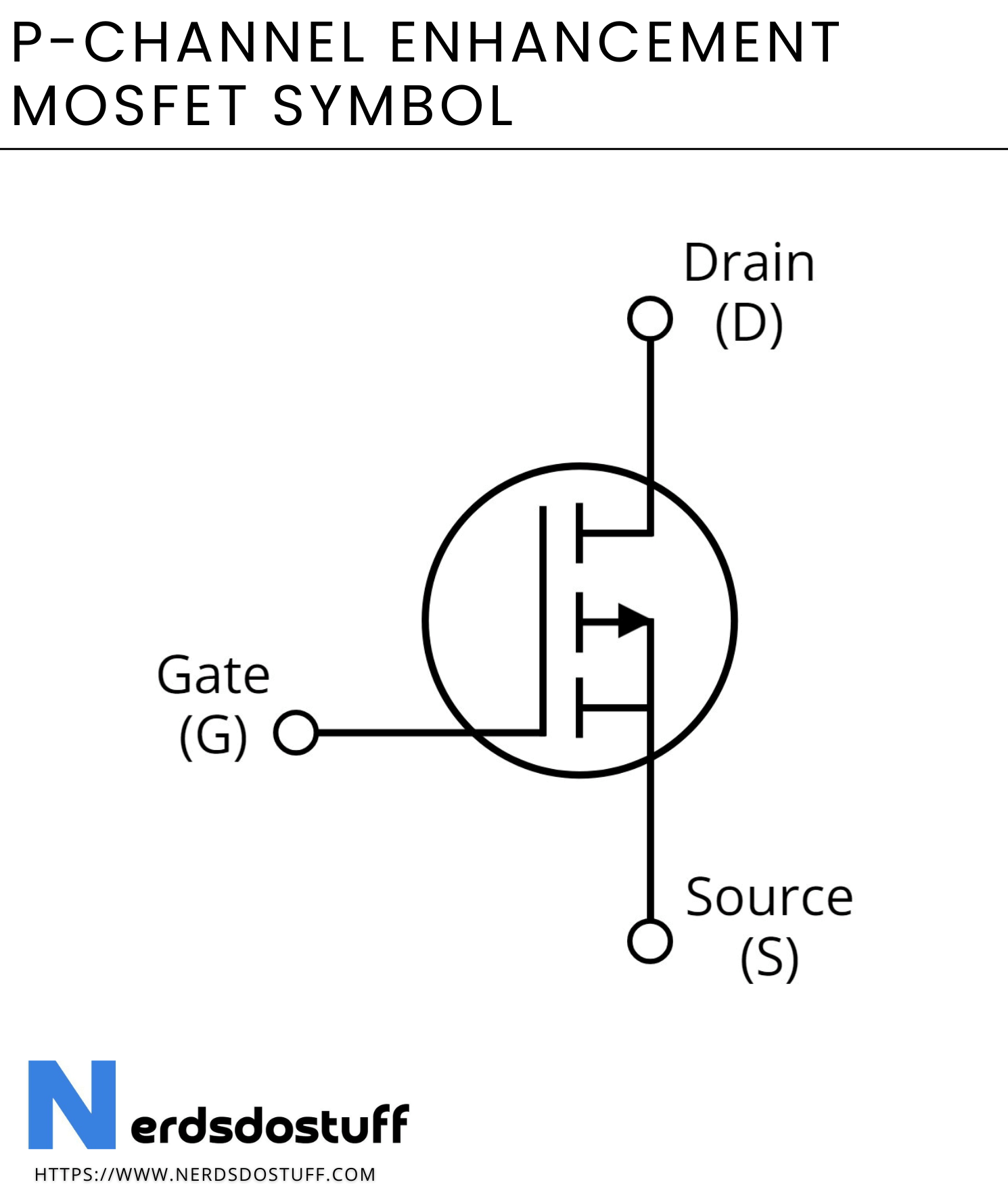
- The Arrow: For a P-channel, it points out from the gate, on the body/substrate connection, indicating the direction of conventional current flow if the body diode were forward biased. More importantly for quick ID, if the arrow is on the Source terminal itself and integrated into the channel line, it also points away from the channel. The key is it’s generally depicted coming from the P-type source towards the N-type body, or just pointing away from the gate on the channel.
- Source (S): This is usually connected to the positive voltage rail in a typical high-side switch configuration. This is where the arrow is.
- Drain (D): This usually goes to your load (my motor, in that old project).
- Gate (G): This is the control. And here’s the kicker for P-channels: you need to pull the gate voltage lower than the source voltage to turn it ON. This was the opposite of N-channels where you pull the gate higher.
Once I really drilled that into my head – P-channel, arrow out, gate goes low to turn on – things started to click. I re-wired my little motor controller circuit, made sure my pull-up resistor was correctly placed to keep it off by default, and then used my microcontroller to pull the gate low when I wanted the motor to run.
And voilà! It worked.
It sounds silly to get stuck on a symbol, but these little visual cues are the language of electronics. Get them mixed up, and you’re speaking gibberish to your components. I guess it’s like those times when I was younger, trying to assemble some flat-pack furniture. The diagrams look simple, but if you miss one little detail in the drawing, you end up with a wobbly table or a drawer that doesn’t close. Same thing here. That P-channel symbol, with its outward-pointing arrow, is a critical piece of information. Now, it’s second nature, but I always respect the basics because they’re the foundation everything else is built on. I even keep a little laminated card with common symbols in my toolkit, just in case my brain decides to have a foggy day.