Alright, let me tell you about my little adventure trying to really get a grip on MOSFET saturation. I’d read about it, seen the graphs, but you know how it is – sometimes you just gotta get your hands dirty to make it click.

My Initial Muddle
So, I was working on a small project, needed to switch a somewhat beefy load with a microcontroller. A MOSFET seemed like the obvious choice. I knew you had to turn it on hard, get it into “saturation” to make it act like a proper switch with low resistance. But what did that really mean in practice? How much gate voltage was “enough”? I was a bit fuzzy on the details beyond just “apply Vgs > Vgs(th)”.
Setting Up the Experiment
I decided to dedicate an afternoon to just this. I didn’t go too fancy. Here’s what I pulled out:
- A common N-channel MOSFET, I think it was an IRFZ44N I had lying around.
- My trusty breadboard and jumper wires.
- A couple of resistors: one for the gate, and a power resistor to act as my “load.”
- My bench power supply – one channel for Vds (the main circuit), another for Vgs (the gate).
- And of course, my multimeter, to measure voltages and current.
My setup was pretty straightforward. Power supply positive, through the load resistor, to the drain of the MOSFET. Source to ground. Then, I used the second power supply channel to apply a variable voltage (Vgs) to the gate, with a small current-limiting resistor (like 1kΩ) just in case, though for Vgs it’s mostly about the voltage.
The Fiddling Begins
Okay, so I set a fixed Vds, say around 5V, across my load resistor and the MOSFET. Then I started playing with Vgs.
First, Vgs at 0V. Nothing. As expected. The MOSFET was off, no current (Id) flowing through the load. My multimeter confirmed this.
Next, I slowly started increasing Vgs. Once I crossed the threshold voltage – Vgs(th), which for this guy is a few volts – I started seeing current flow through the load. The multimeter started showing some milliamps, then tens of milliamps, then hundreds as I nudged Vgs higher. At this stage, if I changed Vgs a little, Id changed a lot. This was the MOSFET acting like a variable resistor, the “linear” or “ohmic” region they talk about, though for switching, you don’t really want to linger here for long when “on”.
Hitting the Plateau – The “Aha!” Moment
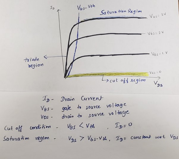
I kept pushing Vgs higher. Let’s say I got to 4V, 5V, 6V… The current (Id) through my load resistor was increasing, increasing… and then, it started to slow down its rate of increase. I pushed Vgs to 7V, then 8V. And here’s the kicker: the drain current (Id) pretty much stopped increasing significantly. It plateaued. My load was seeing a steady current, even if I cranked Vgs up to 10V or 12V (within the MOSFET’s limits, of course!).
That was it! That was saturation in action! The MOSFET was now fully “on.” It was like a water tap opened all the way. Turning the handle (Vgs) further didn’t make much more water (Id) flow because the pipe (the MOSFET channel for that given Vds) was already at its capacity for that main supply voltage (Vds).
I also noticed that the voltage drop across the MOSFET itself (Vds) became very small. That’s what you want for a switch – minimal voltage drop means minimal power wasted as heat in the MOSFET.
What I Learned (The Hard Way, Kinda)
So, what did this little session teach me?

- Saturation isn’t just about exceeding Vgs(th). You need to go significantly beyond it to make sure the MOSFET is truly, deeply saturated, especially if you want that Rds(on) to be as low as advertised.
- The load current in saturation is primarily limited by your VDD and load resistance, not so much by small changes in Vgs (once Vgs is high enough). The MOSFET is essentially a closed switch.
- It’s super important for switching applications. If you don’t drive the gate hard enough to saturate the MOSFET, it’ll operate in the linear region, have a higher resistance, and get hot, potentially burning out. Not good.
- Checking the datasheet for “Vgs for Rds(on)” is a good starting point, but seeing it on the bench really drives it home. For many logic-level MOSFETs, 5V is plenty, but for standard ones, you often need 10V or more on the gate to get the best performance.
It sounds simple now, but fiddling with the knobs and watching the multimeter really cemented the concept for me. Way better than just staring at equations. Sometimes you just gotta do it to understand it.