Okay, so today I wanted to mess around with MOSFETs, specifically looking at how they behave in the triode region. I’ve played with these things before, but never really focused on this specific area, so I figured, why not?

Getting Started
First, I grabbed a basic N-channel MOSFET from my parts bin – an IRF540, I think. Nothing fancy, just something I had lying around. Then, I set up a simple circuit on my breadboard. I’m talking super basic: a power supply, the MOSFET, a resistor to limit the current, and my multimeter to measure some voltages.
The Setup
I connected the positive side of my power supply to the drain of the MOSFET, and then I put that resistor between the source and ground. I wanted to be able to adjust the gate voltage, so I used another power supply for that, connecting it to the gate and ground.
My plan was simple: I’d slowly increase the gate voltage (Vgs) and keep an eye on the drain-source voltage (Vds) and the drain current (Id). I knew that in the triode region, the MOSFET is supposed to act kind of like a variable resistor, so I wanted to see that in action.
Taking Measurements
- I started with Vgs at 0V. Obviously, nothing happened. No current flow, Vds was equal to my supply voltage. Makes sense.
- I started bumping up Vgs, little by little. 0.5V, 1V, 1.5V… still nothing much. The MOSFET was still “off.”
- Then, around 2V or so (the threshold voltage, Vth, for this particular MOSFET, I think it is around 2-4V), I started to see some current! Vds started to drop, meaning the MOSFET was starting to conduct.
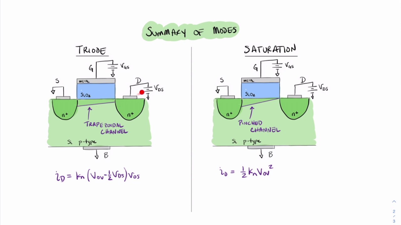
- Now, this is where it got interesting. As I continued to increase Vgs, Vds kept dropping, and Id kept increasing, but not linearly. It was a gentle curve. This was the triode region!
- I took down some numbers. Vgs, Vds, and I calculated Id (using Ohm’s law on the resistor: Id = (Vsupply – Vds) / R). I jotted these down in my notebook.
What I Observed
What I saw was pretty cool. For small values of Vds (less than Vgs – Vth), the relationship between Vds and Id really did look like a resistor. As I increased Vgs, the “resistance” of the MOSFET decreased. It was acting like a voltage-controlled resistor, just like the theory said it would.
I played around with different resistor values and different supply voltages, just to see how things changed. The basic behavior was always the same: as long as Vds was small enough, the MOSFET stayed in that triode region, and I could control the current flow by adjusting Vgs.
It’s one thing to read about this stuff in a textbook, but it’s another thing entirely to see it happen right in front of you. This little experiment really helped solidify my understanding of how MOSFETs work in this particular region.