Alright, let’s talk about these MOSFET regions. It’s one of those things that seems a bit abstract until you actually get your hands dirty and see things work – or not work, which is often how you learn best!
When I first started messing with MOSFETs, I kinda just treated them like simple switches. You put a voltage on the gate, and bam, current flows from drain to source. Easy, right? Well, not quite. I soon found out that things weren’t always behaving as I expected. Sometimes my LEDs were dimmer than I thought they’d be, or a motor wouldn’t get to full speed. That’s when I realized I needed to dig into what these “regions” actually meant in practice.
My First Real Encounter with Regions
I remember working on a little project, trying to control the brightness of a small lamp using a MOSFET and a PWM signal. My initial attempts were… frustrating. The control wasn’t smooth, and sometimes the MOSFET got surprisingly warm. I was just thinking “gate high = on, gate low = off.”
Then, I started looking at the datasheets more closely, not just for the max current and voltage, but at those graphs they show. That’s where these regions started to make a bit more sense, not just as names but as actual operating conditions.
Breaking Down What I Found
So, I basically started experimenting and observing. Here’s how I came to understand these zones, through a bit of trial and error:
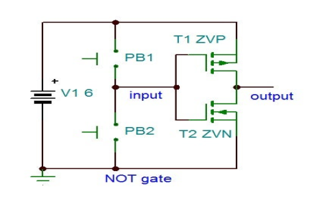
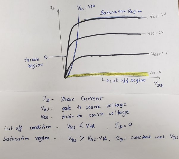
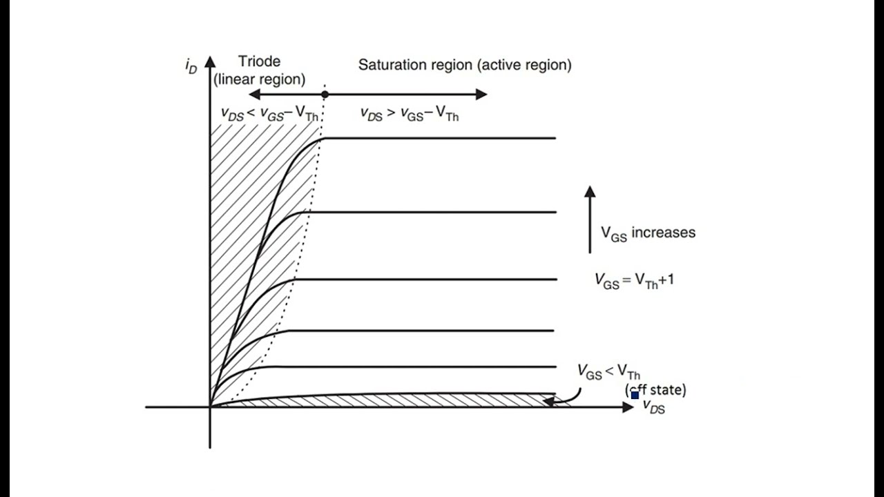
- The “Cut-off” Region: This one was pretty straightforward. If I didn’t apply enough voltage to the gate (that VGS thingy), nothing happened. The MOSFET was basically an open switch. No current flowed from drain to source, or at least, a very tiny leakage current that I usually ignored for my simple projects. This is your “OFF” state. Easy enough. I confirmed this by just not connecting the gate to anything or pulling it low. Light off. Motor still. Perfect.
- The “Ohmic” or “Triode” Region (or “Linear Region” as some call it): This is where things got interesting and a bit tricky. If I applied some voltage to the gate, enough to turn it on, but not quite enough to fully saturate it (or if the drain-to-source voltage VDS was low), the MOSFET started to act like a variable resistor. The amount of current it let through depended not just on the gate voltage, but also on the voltage across the drain and source. It wasn’t just a simple “ON.” This is where my lamp brightness control was supposed to be clever, but also where the MOSFET could get hot if I wasn’t careful, because it was dissipating power if it was resisting current flow. I learned that if I wanted to use it like a voltage-controlled resistor, this was the zone. But for a simple switch, I didn’t want to linger here too long with high currents.
- The “Saturation” Region: This is the sweet spot for using a MOSFET as a switch. If I cranked up the gate voltage (VGS) high enough, the MOSFET would turn “fully on.” It would allow as much current to flow as the load and the MOSFET itself could handle, with very little resistance (that RDS(on) value you see in datasheets). This is your “FULL ON” state. In this region, the current flowing is mostly determined by the load, not so much by small changes in VDS once it’s above a certain point. For my LEDs and motors, getting the MOSFET into saturation meant maximum brightness or speed, and importantly, the MOSFET stayed cooler because it wasn’t resisting much.
Putting it all Together in Practice
So, my big takeaway was this: when I wanted to use a MOSFET as a simple switch (like for turning a motor on or off with a microcontroller), I needed to make sure my gate signal was strong enough to push it decisively into saturation when “ON,” and clearly into cut-off when “OFF.” Lingering in the ohmic region when I intended a full switch-on could lead to inefficiency and heat.
I started paying more attention to the VGS(th) (threshold voltage) in the datasheet, understanding that this is just where it starts to turn on. To get it properly into saturation for switching applications, I learned I usually needed to apply a VGS significantly higher than VGS(th) – often what the datasheet specifies for RDS(on).
It took a bit of fiddling, maybe a few slightly warm components, and staring at those characteristic curves in datasheets, but eventually, the practical behavior of these regions clicked. It wasn’t just theory; it directly impacted how my circuits behaved. And that, for me, is always the best way to learn!