Alright, so I’ve been meaning to share this little project I wrapped up recently. I decided to have a crack at building a MOSFET power amplifier. It’s something I’ve dabbled with before, but this time I wanted to really document, well, mostly for myself, how it all went down. You know, the good, the bad, and the slightly smoky bits.
Getting the Idea and Parts Together
It all started because my old workshop amp finally bit the dust. Instead of just buying a new one, I thought, hey, I’ve got some parts lying around, why not build one? MOSFETs have always been kinda interesting to me for audio stuff – supposed to have a nice sound, or so they say. So, the mission was set.
First up, I had to dig through my component bins. It’s always a bit of an adventure in there. Here’s what I managed to scrounge up for the core of it:
- A couple of IRFP240 and IRFP9240 MOSFETs. Found these still in their anti-static bags from a project I never quite finished years ago. Classic.
- A big ol’ heatsink. Seriously, these things get hot, so you can’t skimp on this. I think this one came off an old server power supply.
- Various resistors and capacitors. My collection is pretty random, so I had to make a few value substitutions here and there, hoping for the best.
- A toroidal transformer. This was the tricky bit. Ended up buying a new one because the ones I had were either too wimpy or the wrong voltage.
- Some perfboard. I wasn’t going to mess around with etching a PCB for this one-off. Keep it simple, right?
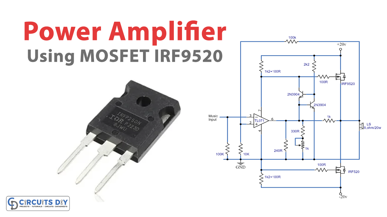
I found a fairly straightforward schematic online – nothing too fancy, a pretty standard Class AB design. Seemed like a good starting point for a hobby build.
The Actual Build Process – Solder and Hope
Then came the assembly. This is where the patience really gets tested. I started by mounting the MOSFETs to the heatsink. Made sure to use thermal paste and mica insulators – don’t want any shorts there, that’s a quick way to a dead MOSFET, and nobody wants that.
Soldering everything onto the perfboard was next. My eyesight isn’t what it used to be, so there was a lot of squinting and double-checking. I tried to keep the signal paths short and the ground connections solid. It looked a bit like a rat’s nest for a while, not gonna lie, but I slowly tamed it. There were a couple of moments where I soldered a resistor in the wrong spot, or a capacitor backwards. Had to get the desoldering pump out. Fun times.
Wiring up the power supply was next. Rectifiers, big filter capacitors – the works. You gotta be careful with this part, mains voltage is no joke, and even the DC side can pack a punch. I triple-checked all those connections. Seriously.
First Power-Up and the Smoke Test (Almost)
Okay, moment of truth. I always get a bit nervous at this stage. Before connecting any speakers or audio input, I did the classic “dim bulb tester” trick. Basically, you put a lightbulb in series with the mains input. If there’s a major short, the bulb lights up brightly, and hopefully saves your components from going pop.
Flicked the switch… and the bulb glowed dimly then settled down. Phew! No immediate fireworks. That’s always a good sign. I let it sit for a bit, carefully touched the heatsink – cool. MOSFETs – cool. Okay, so far so good.
Next, I checked some key voltages with my multimeter. They were roughly in the ballpark of what the schematic suggested. Good enough for me to proceed!
Hooking It Up and Making Some Noise
Time to actually see if this thing makes music. I connected an old MP3 player to the input and a pair of sacrificial test speakers to the output. You know, the kind you don’t mind blowing up if things go horribly wrong. Took a deep breath and slowly turned up the volume.
And… sound! It actually worked! Not gonna say it was the cleanest sound right off the bat. There was a bit of hum, and one channel seemed a bit weaker than the other. So, back to troubleshooting. The hum turned out to be a ground loop I’d accidentally created. Re-jigged some wiring, and that improved things a lot. The channel imbalance was a dodgy connection on one of the input potentiometers. A bit more solder, and it was sorted.
After a bit of tweaking the bias current (which, by the way, you have to do carefully, monitoring the heatsink temperature), it started to sound pretty decent. For a home-brew amp built on perfboard with parts from my junk box, I was pretty chuffed. It’s got that slightly warm sound that MOSFETs are known for, and plenty of power to drive my workshop speakers louder than I’d ever need.
So yeah, that was my little adventure into building a MOSFET power amplifier. It was a fun process, a few frustrating moments, but ultimately rewarding. There’s something special about listening to something you built yourself, imperfections and all. Now, what to build next?