Okay, here’s my take on a blog post about a high-side MOSFET switch, written in a casual, practical style, and using the proper HTML tags:
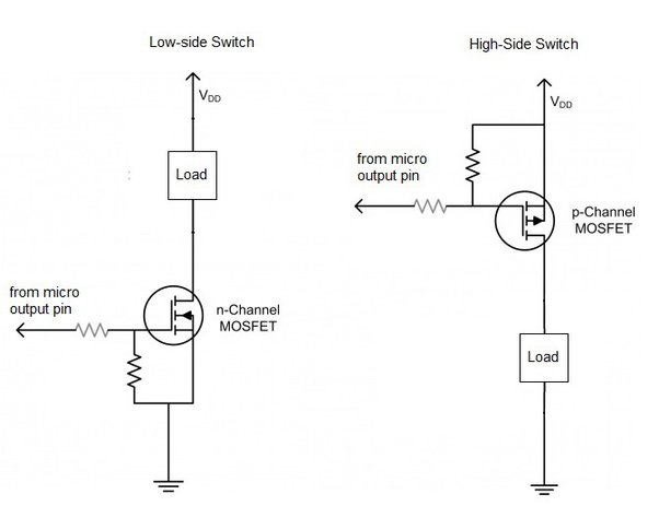
So, I wanted to control a load from the “high side” – meaning, I wanted to switch the positive voltage going to the load, rather than switching the ground connection. I’ve done low-side switching tons of times with an N-channel MOSFET, super easy. But high-side? That’s a different beast.
The Problem with Just Using an N-Channel
My first thought, like always, was to grab an N-channel MOSFET. I mean, they’re everywhere, and I’m comfortable with them. I hooked it up, thinking I was clever. Put the load between the positive supply and the MOSFET’s drain, source to ground, and figured I’d just send a signal to the gate. Nope. Didn’t work at all like I expected. Barely turned on, if at all.
It took me a minute to realize the problem, my gate voltage has to be a minimum amount higher than source, and with it connected to ground, it can’t ever be higher than the voltage at drain!
Enter the P-Channel MOSFET
After a bit of digging around and some “aha!” moments, I figured out I needed a P-channel MOSFET. These things work the opposite way from N-channels. To turn them off, you pull the gate voltage high (close to the supply voltage). To turn them on, you pull the gate low (towards ground). This seemed much more promising.
My Setup
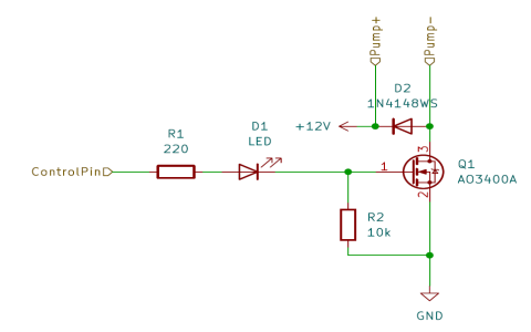
Here’s what I ended up doing:

- MOSFET: I grabbed a P-channel MOSFET.
- Load: For testing, I just used a simple LED and resistor, but this could be anything – a motor, a bigger light, whatever.
- Pull-up Resistor: I connected a resistor (something like 10k ohms worked fine) between the MOSFET’s gate and the positive supply. This is super important. It ensures the MOSFET is off by default.
- NPN Transistor: To control the P-channel’s gate, I used a little NPN transistor (like a 2N3904 – I have a bunch of these lying around). The collector went to the P-channel’s gate, the emitter to ground, and the base got my control signal (through another resistor, of course – gotta limit that current!).
How it Works
The basic idea is this:
- When I want the load off, I don’t send any signal to the NPN transistor’s base. The pull-up resistor keeps the P-channel’s gate voltage high, so it stays off.
- When I want the load on, I send a signal to the NPN transistor’s base. This turns the NPN on, which pulls the P-channel’s gate voltage low (towards ground). This turns the P-channel on, and power flows to the load!
The Result
It worked! I could now reliably switch my load from the high side. It felt good to finally get it working after that initial confusion with the N-channel. It’s a little more complicated than a low-side switch, but not by much, and it’s definitely a useful trick to have in your toolbox.
It’s important to take the voltage into account when selecting your parts. You don’t want to apply to much and fry your components! I made sure to double check the data sheets of the MOSFET and transistor before applying power.