So, I decided to mess around with an N-channel MOSFET as a switch. You see these things everywhere, and people talk like they’re magic. Just hook it up and boom, you’re controlling big loads with a tiny signal from your microcontroller. That’s the dream, right?
My First Go
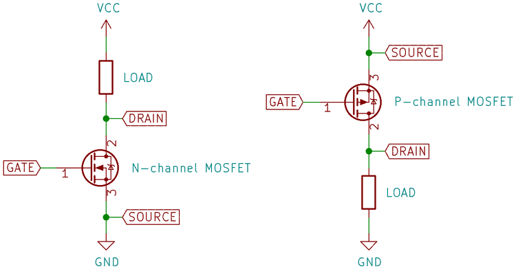
I grabbed a common MOSFET I had lying around – pretty sure it was an IRFZ44N, one of those workhorse types. My goal was simple: turn an LED strip on and off using an Arduino. Sounds basic, and honestly, I thought it would take me all of five minutes. I’ve seen the diagrams a million times. Gate to the Arduino pin, drain to the negative side of the LED strip, source to ground. The positive side of the LED strip, of course, went to the power supply.
I wired it all up on my breadboard. Double-checked my connections. Wrote a super simple Blink sketch, but instead of blinking the onboard LED, it was toggling the pin connected to the MOSFET gate. Uploaded the code. And… nothing. Well, not exactly nothing. The LEDs were just on. All the time. My “switch” was stuck in the “on” position, apparently.
What Went Wrong?
Okay, first thought: I fried the MOSFET. It happens. Or maybe it was a bad one to begin with. So I swapped it out for another one from the same bag. Same result. LEDs glaring at me defiantly. My super simple switch wasn’t switching. It was just… being.
I started thinking, maybe the gate isn’t being pulled low properly. When the Arduino pin goes LOW, the gate should be at 0V, right? And the MOSFET should turn off. I remembered reading about pull-down resistors. So, I grabbed a 10k resistor and put it between the gate and ground. The idea is that this resistor makes sure the gate is truly at 0V when the Arduino pin isn’t actively pulling it HIGH.
Tried it again. And hey, it worked! The LEDs started blinking on and off with the Arduino signal. Success! Or so I thought. This is where it got a bit more interesting, or annoying, depending on your perspective.

This whole adventure reminded me of a job I had a while back. We were building this control panel for some industrial machine. My boss at the time, old fella named Dave, insisted we use these ancient mechanical relays for everything. I suggested using MOSFETs for some of the DC loads, make it more compact, faster switching, no clicking sounds. He just looked at me over his glasses and said, “Son, these relays have been working since before you were born. We stick with what works.” I guess he had a point about reliability in that context, but it felt like we were stuck in the dark ages. Trying to get this MOSFET to behave felt a bit like arguing with Dave – you think it should be straightforward, but there’s always some old wisdom (or forgotten detail) you’re missing.
More Details Emerge
Back to my blinking LEDs. While the pull-down resistor fixed the “always on” issue, I noticed something else when I tried to use PWM to dim the LEDs. The dimming wasn’t very smooth at the lower end. The MOSFET wasn’t turning on quite as sharply or as fully as I expected with the 5V logic from the Arduino. That IRFZ44N, while a good MOSFET, is not always the best choice for direct logic-level drive from a 5V microcontroller if you want it fully saturated (turned on hard) without any fuss. It often prefers a bit more voltage on the gate, like 7-10V, to really get going with minimal resistance.
So, for a simple on/off, the 5V with a pull-down was fine. But for finer control like PWM dimming, especially with a 3.3V microcontroller, you really need to pay attention to the MOSFET’s gate threshold voltage (Vgs(th)) and the voltage needed for full enhancement. Or use a specific “logic-level” MOSFET designed to work well with 3.3V or 5V gate signals. Some people even add a small BJT transistor circuit to drive the MOSFET gate with a higher voltage if they only have standard MOSFETs on hand.
Final Thoughts
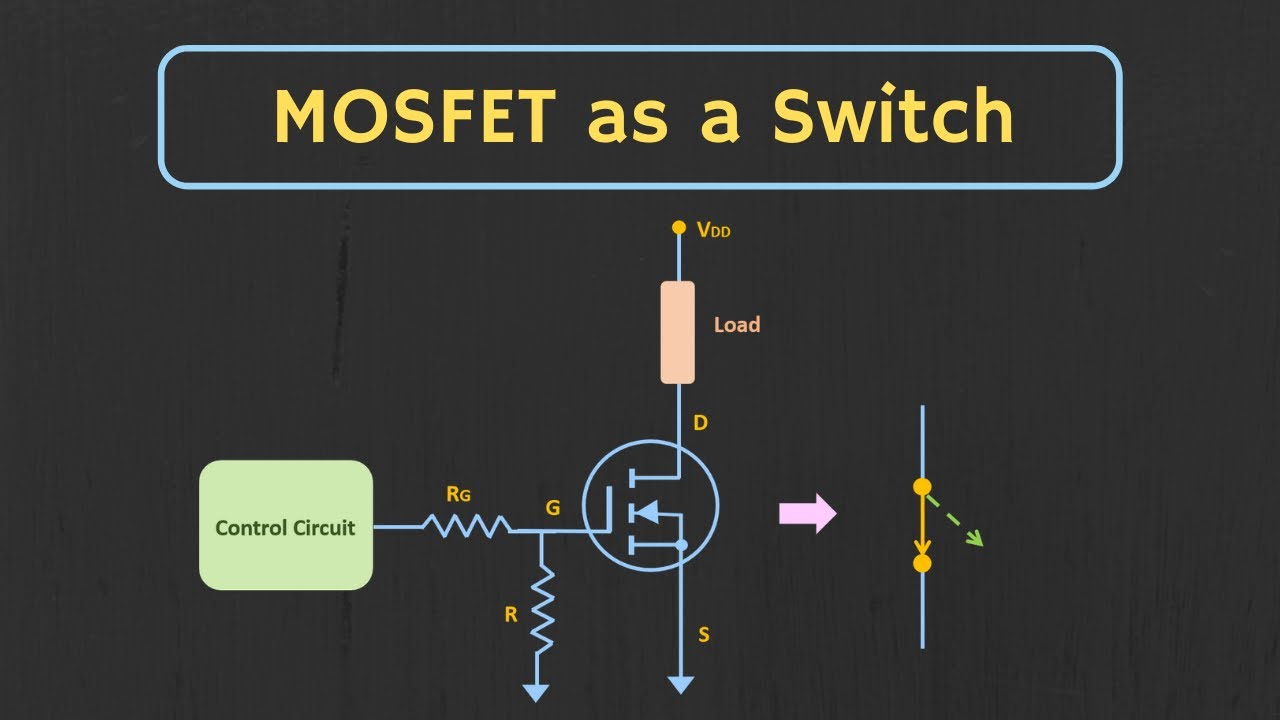
So, my little experiment was a good reminder. N-channel MOSFETs are great switches, but they’re not always “plug and play” without a little thought. You gotta consider things like:
- Floating gates: Always use a pull-down resistor (between gate and source) if your microcontroller pin might float, or if you want to ensure the MOSFET is off when the controller is starting up or reset. Or a pull-up resistor (between gate and V+) for a P-channel used in high-side switching if you want it off by default.
- Gate drive voltage: Make sure your control signal voltage is enough to turn the MOSFET on fully, especially if you’re trying to minimize heat and maximize efficiency. Check the datasheet for Vgs(th) and the Rds(on) at your intended gate voltage.
- Gate resistor: Sometimes, a small resistor in series with the gate (between the microcontroller pin and the gate) is a good idea. It can limit the current rushing into the gate capacitance, protecting your microcontroller pin, and can also help prevent ringing or oscillations. I didn’t need it for this slow LED blinking, but for fast switching, it’s often essential.
It wasn’t as simple as I first thought, but getting it to work reliably was pretty satisfying. And it definitely beat trying to convince old Dave to try something new back in the day!