Fed up with those little regulators, right? LM7805s and LM317s turning into tiny frying pans when you actually ask them to do some work. That was me. Needed something that wouldn’t sweat so much for this one project I was messing with. My previous setup, it just couldn’t handle the current without getting ridiculously hot, and I was tired of babysitting it or worrying about a meltdown.

So, I figured, why not try a MOSFET? Heard they could handle more current and stay cooler, at least that was the theory. Had a few N-channel ones lying around in my parts bin from some other harebrained idea that probably didn’t pan out.
Kicking Things Off – The Messy Bench
First thing, I dumped my component drawers out. You know how it is. Found some N-channel MOSFETs – I think I grabbed an IRF540N, pretty common. Also scrounged up a couple of Zener diodes, the usual handful of resistors you always seem to need, and a potentiometer for tweaking things. Seemed like enough to get a basic circuit going.
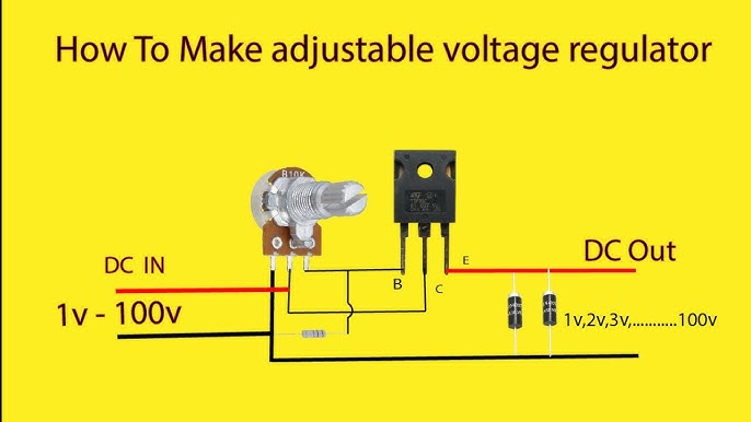
The plan in my head was simple, or so I thought at first. Use a Zener diode to get a steady reference voltage. Then, the MOSFET acts like a variable resistor, or a tap, controlling the flow. And you need some kind of feedback loop from the output back to the MOSFET’s gate to adjust that tap. Easy peasy, right? Yeah, right. Turns out, the devil’s in the details, as always.
The Actual Build – Where Things Got Real
Dragged out the trusty breadboard. Always, always breadboard stuff like this first. If you don’t, you’re just asking for a world of desoldering pain later on, trust me on this one. And boy, did I wrestle with that gate voltage for the MOSFET. MOSFETs are kind of finicky beasts with their gates; they’re voltage-controlled, not current-controlled like a good old BJT where you just pump some current into the base and it does its thing. You gotta get that gate voltage just right.
My first attempt? The output voltage was dancing all over the place. Seriously, it looked like a drunk sailor trying to walk a straight line on my multimeter. Classic. I figured either my Zener reference wasn’t as stable as I hoped, or my feedback loop was just plain garbage. So, I started swapping resistors in the voltage divider network. That potentiometer I found earlier was a lifesaver here, let me tell you. It let me tune the output voltage on the fly instead of soldering and desoldering resistors a million times.
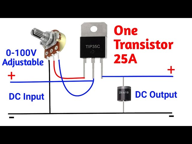
- The main workhorse was that IRF540N MOSFET.
- For the reference, I used a 5.1V Zener diode, nothing fancy.
- A couple of resistors for the voltage divider that senses the output, and another one to limit current to the Zener. You always need more resistors than you think.
- And that 10k potentiometer for adjusting the output. Standard stuff, really.
I set up the Zener with its current-limiting resistor to give me that 5.1V reference. Then, I built a simple error amplifier. You can use an op-amp for this, and it’s probably better, but I initially just threw together a couple of transistors to make a differential amplifier to see if I could get the basic principle working. This compares a fraction of the output voltage (from my voltage divider) with the Zener reference. The output of this error amp then drives the gate of the MOSFET. If the output voltage tries to dip, the error amp tells the MOSFET to turn on a bit more. If it tries to go too high, it tells the MOSFET to ease off. That was the idea, anyway.
Did It Work? The Moment of Truth
After a bit of tweaking, and maybe a few choice words muttered under my breath, I hooked it up to my bench power supply. I think I was feeding it around 12V in, and I was aiming for a steady 5V out. Started loading it down with some chunky power resistors to draw some current. All the while, I kept one eye glued to my multimeter reading the output voltage.
And what do you know? It actually held! Pretty stable too, even as I varied the load a bit. The output voltage wasn’t perfectly rock solid down to the last millivolt, but it was way better than I expected for a home-brew job on a breadboard.
The best part? The MOSFET was just lukewarm to the touch. That was the big win for me. Now, let’s be clear, this isn’t some super-duper efficient switching regulator. It’s still a linear regulator at heart, just using a MOSFET as the pass element instead of a BJT or a dedicated IC. So, if you’re dropping a ton of volts from your input to your output (like, say, 24V in to 5V out at high current), that MOSFET is still gonna get hot, make no mistake. You can’t cheat physics. But for my application, where the voltage drop wasn’t massive, the heat improvement over the old LM317 was night and day.
One thing I had to constantly remind myself: MOSFETs are sensitive little things. Static electricity absolutely loves to kill ’em, so I tried to be careful. And yeah, if you are planning on pushing serious current through it, or if you do have a big voltage drop, you absolutely need to slap a heatsink on that MOSFET. It’s common sense, but it’s the kind of common sense that’s easy to forget when you’re in the zone and just want to see if the darn thing works.
So, What’s the Takeaway?
Look, making your own MOSFET voltage regulator? It’s a decent little project and a good learning exercise. It ain’t black magic, but it sure ain’t plug-and-play like just dropping in a 7805 either. It definitely solved my “regulator on fire” issue for that particular project, and it gave me a more robust solution. It’s a good trick to have in your back pocket if you need something a bit more custom or something that can handle more current than your typical off-the-shelf IC regulators, and you don’t want to dive into the complexity of designing a full-blown switching power supply from scratch. Just be ready to tinker and fiddle with values. And breadboard it first. Did I say breadboard it? Good. Saves a lot of headaches down the line.