Okay, so today, I’m diving into this whole “MOSFET small signal” thing. Sounds a bit complicated, but it’s actually not that bad once you get the hang of it. I mean, I’m no expert, but I wanted to see what it’s all about.
I started by looking around to find some info on the internet, and there’s a lot out there! But, honestly, a lot of it was way over my head. So, I decided to just jump in and get my hands dirty.
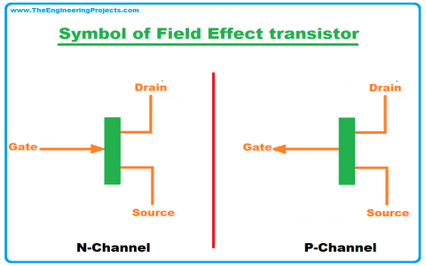
First things first, I needed a MOSFET. I grabbed a basic one I had lying around. Then, I set up a simple circuit on a breadboard. Nothing fancy, just a power source, a resistor, and the MOSFET. I started by using the old meter, set it to DC and tested the voltage across the pins, so many weird values. But, at least it is giving me something.
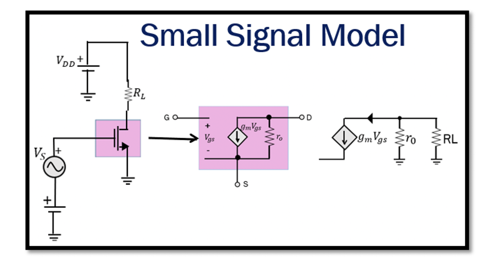
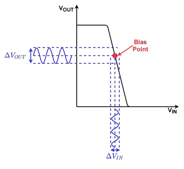
Now, the “small signal” part is where it gets interesting. Basically, we’re talking about tiny changes in voltage and current. The idea is to see how the MOSFET responds to these small changes. This is important because in a lot of circuits, like amplifiers, you’re dealing with these small signals.
I played around with different input voltages, making very small adjustments. I hooked up my oscilloscope, just a cheap one, to see what’s going on. It is cool to see how the output changes with these small input changes. I kept track of the input and output voltages and tried to see if there was any relationship.
I tried to change the gate voltage a little bit and watched what happened to the drain current. It’s like, a small change at the gate can cause a bigger change in the current. That’s the whole idea of amplification, right? And this MOSFET is doing it. And the readings are making more sense now!
Here’s what I did step-by-step:
- Set up the basic circuit with the MOSFET.
- Applied a small DC bias voltage to the gate to get it into its active region.
- Added a small AC signal on top of the DC bias. I used a signal generator.
- Observed the output signal at the drain with the oscilloscope.
- Measured the gain, which is basically how much the output signal is amplified compared to the input.
I messed around with different bias voltages and signal amplitudes, noting down the results each time. It took a while, but I started to see a pattern. There’s definitely a relationship between the bias voltage, the input signal, and the output.
The Results
After a lot of trial and error, I was able to get some decent results. I could see the small signal being amplified, and I could even calculate the gain of the MOSFET in my setup. It wasn’t perfect, and there was some noise in the measurements. It is all good for the first time messing around with this.
So, that’s my little adventure with MOSFET small signals. I’m sure there’s a ton more to learn, but this was a pretty good start. It’s cool to see how these little devices can do so much. I just want to share my little project with you guys! Hope you find this fun!