My Little Adventure with MOSFETs
So, I was tinkering with some circuits the other day, as one does when trying to avoid actual chores. I had a bunch of MOSFETs lying around from some old project, and I remembered reading somewhere that these things aren’t just on/off switches. They can do more, apparently.
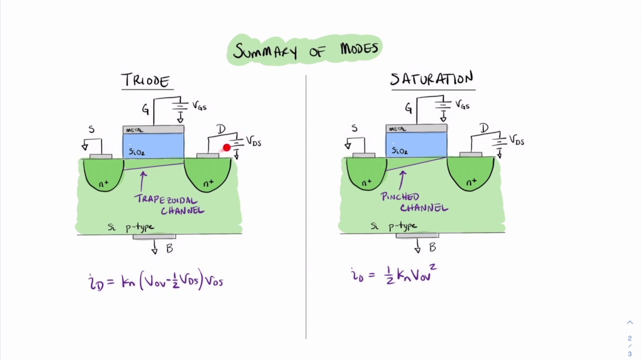
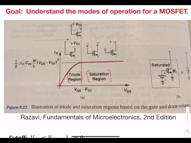
I got curious about this “triode region” or “linear region” – people call it different things, which is confusing, right? Anyway, the main idea I latched onto was that you could make a MOSFET behave like a resistor whose resistance you can change with a voltage. A voltage-controlled resistor! That sounded pretty cool, and potentially useful for, I don’t know, something.
Getting My Hands Dirty
So, I decided to give it a whirl. I didn’t have a fancy lab setup, just my trusty breadboard, a power supply, a couple of multimeters, and one of those N-channel MOSFETs. I think it was a 2N7000, or something equally common. You know, the kind you buy in bulk and then find everywhere.
My plan was simple:
- Hook up the MOSFET with a small voltage across its drain and source. Really small, that’s what they said was important for this triode thing.
- Then, I’d apply a separate voltage to the gate.
- I’d measure the current flowing through the MOSFET and see how it changed as I fiddled with the gate voltage.
The Setup Was a Bit Messy
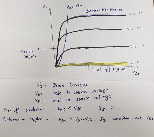
Honestly, my breadboard looked like a rat’s nest, as usual. Wires everywhere. I was half expecting something to smoke, but luckily, it all held together. I made sure the gate voltage was above the threshold voltage – that’s the magic number you need to even get the MOSFET to wake up.
What Happened Next?
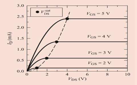
And you know what? It actually sort of worked! When I kept the drain-to-source voltage (Vds) low and started slowly increasing the gate-to-source voltage (Vgs), I could see the current (Ids) going up. It felt like I was opening a tap wider and wider.
It wasn’t a perfect, straight-line relationship like a fixed resistor, especially as I pushed the voltages. But in that small Vds range, it definitely behaved like its resistance was decreasing as I increased the Vgs. Pretty neat! It was like having a little knob to control how much current could flow, but the knob was another voltage.
I tried it with a little LED too, putting the MOSFET in series, and by tweaking the gate voltage, I could dim the LED. It wasn’t super smooth like a proper PWM dimmer, but it showed the principle. It felt more “analog-y” if that makes sense.
My Big Takeaway
It’s one thing to read about these operating regions in a datasheet or a textbook, all those graphs and equations. But actually wiring it up, even crudely, and seeing it respond to my inputs – that makes it click. It’s like, “Oh, so that’s what they mean!”
I don’t think I’ll be designing any high-precision variable resistors with this method anytime soon. My setup was way too basic for that. But it was a fun little experiment. It just shows you these components we use all the time have these different personalities, depending on how you treat them. Kinda like people, I guess. You just gotta find the right way to talk to them, or in this case, apply the right voltages.
Anyway, that was my afternoon. Now, what to try next? Maybe I’ll finally figure out op-amps properly. Or maybe I’ll just stare at a blinking LED for an hour. Who knows!