Alright folks, grab a cuppa coffee, ’cause today I got my hands dirty again. This time, it was all about these MOSFET current mirror thingies. Kept hearing they’re super useful for copying currents, but honestly? I was confused as heck. Four different ways? Which one do you even use? Felt like staring at spaghetti.
First Thing First – Grabbed My Gear
Right, pulled out my messy toolbox. Dug around for MOSFETs – found a couple of N-channel ones, some random resistors probably of the wrong value, my crusty old breadboard, wires everywhere, and that trusty, slightly broken power supply unit. Figured I might as well just jump in and build something. Readin’ about it wasn’t cutting it.
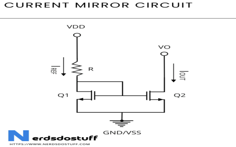
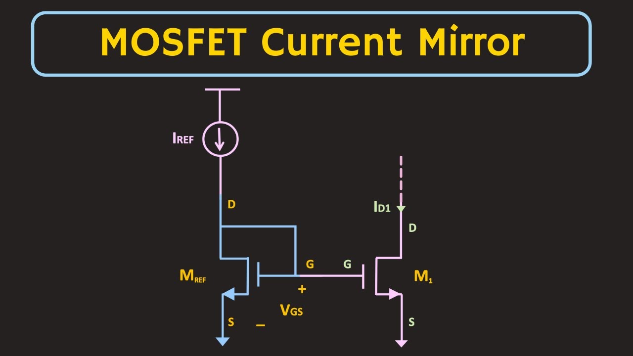
The Simple One Didn’t Stay Simple
Started with what seemed the most basic setup. Just two MOSFETs, right? Hooked ’em up kinda like in the diagrams I half-remembered. Connected the first one, set a current through it using a resistor and the power supply. Okay, cool. Then hooked the second MOSFET so its gate was tied to the first one’s gate. Theory says it should magically copy that current. Did it? Nope. Got barely anything flowing out the second one! Poked at my connections – yep, hooked up drain and source right? Thought I did. Frustrating. Scratched my head for ages. Realized maybe the MOSFETs weren’t twins enough. Learned real quick that they gotta be matched, really close, or this simple setup spits in your face.
Added a Resistor – Did It Help?
Fine! Read online that adding a resistor to the source of the second MOSFET sometimes fixes stuff. Soldered in a resistor, hoping. Powered it up again. The current out the second one went up… but now it was way higher than the original! Like, outta control. Messed with resistor values – too big, nothing happened; too small, went nuts. This felt worse somehow. Less predictable. Thought I broke my power supply at one point.
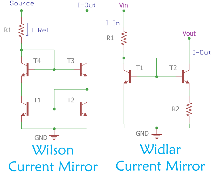
Enter the Third Wheel (Another MOSFET!)
Okay, deep breath. Took down the mess. Started again, but now with a third MOSFET. Built what they call the Wilson current mirror. Looked way more complicated on the breadboard, wires crossing everywhere like a bird’s nest. Powered it up nervously. Measured the input current, measured the output… waited… and boom, it was actually copying it pretty well! Much closer anyway! Finally some success! Stable too, didn’t jump around when I nudged the power supply voltage a bit. Happy dance moment, even though it needed that extra transistor.
Got Fancy With Four Transistors?
Feeling cocky now. Figured, why not try the fourth one? The cascode mirror. Grabbed another MOSFET. This time, stacked them on top of each other, drain to source kind of thing. Read somewhere this helps keep the voltages more steady, makes the copy even better. Build was messy. Double checked all connections twice. Powered it up… it worked! Copied the current even more accurately than the Wilson. Sweet! But, gotta say, it felt like overkill for most simple stuff. More parts, more points of failure.
So What Did I Learn?
- Simple Mirror: Needs matching transistors REALLY bad. Easy to set up, easy to mess up.
- Resistor Version: Tried to help control, ended up being a pain itself. Not a fan.
- Wilson (3 Transistors): First one that worked reliably for me. Needs extra parts, but copies well.
- Cascode (4 Transistors): Works best, super accurate copying, even less sensitive to power supply bumps. But seriously complicated for the breadboard. Feels like a power tool when a wrench would do.
Honestly, most of the time now, if I just need a decent current copy and the current isn’t huge, I just reach for the Wilson setup. It’s predictable. The simple one? Maybe for super rough stuff or with exactly matching transistors. The cascode? Maybe if I ever build something super precise, like, I dunno, a fancy sensor driver. Building ’em all side-by-side was the key – seeing exactly where each one stumbled and shined. Theory finally clicked after my fingers got singed. That’s always the way, ain’t it?