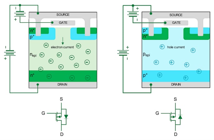
Alright, so I finally got around to playing with one of those N-channel MOSFETs I had lying in my parts bin. Been meaning to figure these things out properly for a little project, something where I need to switch a bit more current than my usual little Arduino pin can handle directly. You know how it is, you collect these bits and pieces, and then one day, you actually need ’em.

Getting Started with the MOSFET
First thing, pulling it out of the anti-static bag. It’s just a little three-legged guy, looks simple enough. But you gotta know which leg does what, right? Gate, Drain, Source. Sometimes the marking is clear, sometimes you’re squinting or hunting down a datasheet online. Took me a few minutes clicking around to find the right diagram for the specific number stamped on this one – a bit annoying, but got there in the end. Pinned it down: Gate on the left, Drain in the middle (and the big tab), Source on the right. Okay, good.
Hooking it Up – The Breadboard Mess
Next, grabbed my breadboard. Love these things for quick tests. Plonked the MOSFET in, spanning the center gap. Needed something to switch, so I grabbed a simple LED and a resistor. Standard test circuit, really.
Here’s how I wired it up, roughly:
- The Source pin (the right leg) went straight to the ground rail of my breadboard. Easy peasy.
- The Drain pin (the middle leg) got connected to the negative leg (cathode) of my LED.
- The positive leg (anode) of the LED went to one end of a current-limiting resistor (picked a 220 ohm one, standard value).
- The other end of the resistor connected to the positive power rail. I used a 5V power supply for this test.
- The Gate pin (the left leg) is the control. For now, I just attached a loose jumper wire to it. This is the magic button.
Double-checked my connections. Didn’t want any magic smoke escaping. Power supply ground to breadboard ground, power supply positive to breadboard positive rail. Looked okay.
The Moment of Truth – Testing Time
Okay, switched on the 5V supply. The LED stayed off. Good sign! That means the MOSFET isn’t conducting when the Gate isn’t getting any voltage (or rather, when it’s effectively at ground potential, floating gates can be weird but let’s not get into that). It’s ‘off’.

Now for the test. Took that loose jumper wire connected to the Gate and touched it to the positive 5V rail on the breadboard. And boom! The LED lit up nice and bright. It worked! The MOSFET turned ‘on’, letting current flow from the Drain to the Source, completing the circuit for the LED.
Then, I pulled the Gate jumper wire away from the positive rail. Poof! The LED went dark again. Connected the Gate jumper to the ground rail just to be sure it was properly off. Yep, stayed off. It’s basically acting like a tiny electronic switch, controlled by the voltage on the Gate.
Final Thoughts – Simple and Useful
Honestly, pretty straightforward once you figure out the pins. It just sits there, blocking current, until you give that Gate pin a little voltage kick (relative to the Source), and then it opens the floodgates. Handles more current and voltage than a little microcontroller pin could ever dream of switching directly.
Definitely see why these are so popular. Simple to use, does the job. I can already think of a few places I could use this, like controlling some brighter LED strips or maybe a small DC motor. Glad I took the time to actually hook one up and see it work with my own hands. Another useful little gadget in the toolkit!

