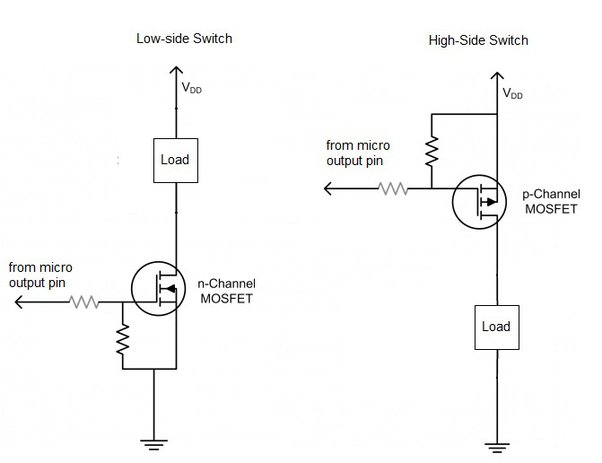
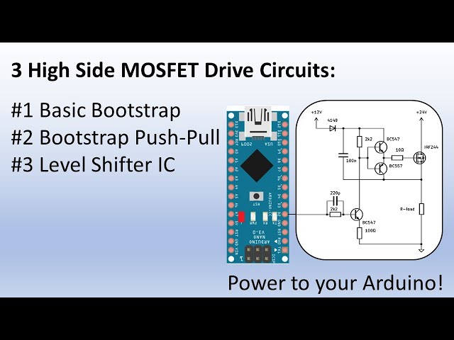
Alright folks, buckle up. Today I wanna talk about messing with these high-side switch things using MOSFETs. Sounded fancy, right? Truth is, I just needed a reliable way to control a 12V motor from my little 3.3V microcontroller. Kept frying stuff. Needed a fix.

Digging Out the Parts Bin Chaos
First step? Raid the parts bin. Total mess in there. Dug through boxes of random junk. Found some N-channel MOSFETs. Okay, cool. Found my trusty breadboard, covered in last month’s dust bunnies. Grabbed a resistor pack, hoping the right value was in there. Scratched around for some wires. Wires everywhere, never the right length. Typical.
Basic plan I started with:
- MCU pin (3.3V, can’t handle much)
- MOSFET (the three-legged thingamajig)
- A resistor (gotta limit that MCU pin current)
- The load (my needy 12V motor)
- 12V Power (simple wall adapter)
Soldering Iron Smells and Frustration
Okay, time to poke holes in the breadboard. Connected the MCU pin to the resistor. Resistor goes to the MOSFET’s leg – the gate pin, I think it’s called. Used a 10k ohm resistor. Seemed safe. Then hooked the motor between the 12V positive and the MOSFET’s drain pin. Source pin straight to ground. Last step: connected the MCU ground and the 12V power ground together. Basics, right?
Powered up the microcontroller. Code was just a simple “pin HIGH for 5 seconds”. Hit upload… nada. Motor dead as a doornail. Nothing. Zilch.
Checked the voltage at the gate. MCU pin was high, barely 3.3V there. Hmm. Measured the gate voltage with my meter. Read a measly 2.5V or something stupid. Not enough juice to properly flip that MOSFET switch fully open, especially under load. Felt pretty dumb. Facepalm moment.

Adding the Missing Piece: The Gate Kicker
Remembered people talking about a “pull-up resistor”? Needed a way to really slam the gate to the full 12V when turning the MOSFET ON. Went back to the resistor box. Found a smaller resistor, like 4.7k. Yanked the old 10k resistor off the gate.
Now did this: The MCU pin still connects to the gate through a 4.7k resistor. BUT. Added another resistor from the gate… wait for it… straight to the 12V rail! Used another 10k for that one.
This felt weird. How can the gate get pulled UP to 12V without frying the tiny MCU pin?
Added a small signal diode too. Cathode towards the MCU pin, anode towards the MOSFET gate. Basically, the diode blocks the 12V from sneaking back into the MCU when the MOSFET should be off.
Finally, Sweet Success!
Power on again. Heart in mouth. MCU pin goes HIGH… BOOM! Motor spins up like a champ! Measured gate voltage: sitting solidly at almost the full 12V. Perfect.

MCU pin goes LOW? Motor stops dead instantly. Diode and the two resistors do their magic, dropping the gate voltage down to ground level. MOSFET shuts off hard.
Tried it maybe 20 times. Worked every single time. No magic smoke. Microcontroller pin happy as a clam. Felt so satisfying after the initial mess-up. This simple trick was the missing link! Much, much easier to understand when you wrestle it onto a breadboard yourself. Anyone else wrestle with high-side switches? What tripped you up? Drop your tales below!

