Alright, so today I wanted to chat a bit about something that used to trip me up quite a bit when I was starting out with more complex circuits: those MOSFET symbols in schematics. You know the ones, with the three legs and sometimes an arrow, sometimes a broken line. For a while, they just looked like weird little drawings to me, and I’d just hope for the best.
I really hit a wall when I was trying to build this little power switching project for a custom LED array. Couldn’t get it to work, and I suspected I was reading the schematic all wrong, probably mixing up my MOSFETs. That’s when I figured, okay, time to actually sit down and get these symbols straight in my head.
Figuring Out the Main Parts
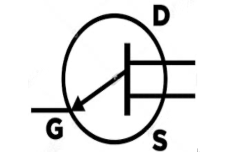
So, the first thing I did was just focus on the three connections. Every MOSFET symbol, pretty much, has these. They call ’em Gate, Drain, and Source. That wasn’t too bad. The Gate is kinda like the tap handle, you know, it controls the flow. The Drain and Source are where the main stuff flows through. Simple enough, I thought. At least that was a start.
That Pesky Arrow: N-Channel or P-Channel?
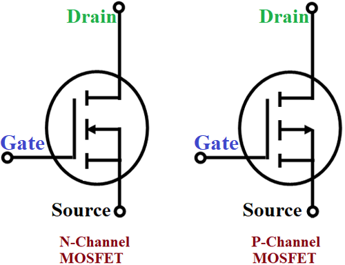
Then came the arrow. This was a biggie for me. Some symbols had it pointing in, some pointing out from the main channel part. It took me a bit of staring at different diagrams and a few datasheets that I barely understood back then. But then it clicked, kind of suddenly. If the arrow on the Source leg points IN towards the channel, it’s an N-channel MOSFET. If that arrow points OUT from the channel, it’s a P-channel.
I literally had to draw a few of these side-by-side on a scrap piece of paper and mutter “arrow in, N-channel; arrow out, P-channel” to myself like a crazy person until it stuck. It’s a small detail, but man, it changes everything about how the thing works and how you hook it up.
Solid Line or Broken Line? Enhancement vs. Depletion
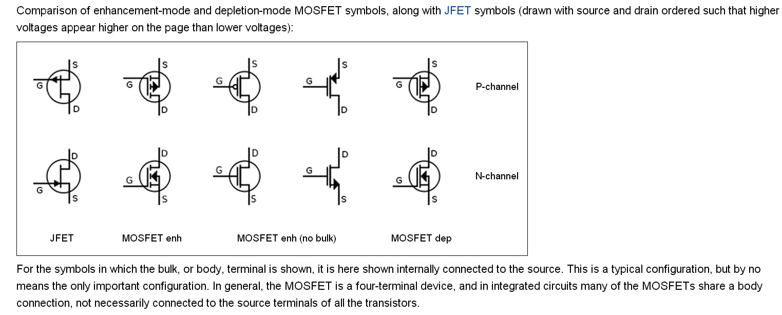
The next hurdle was this line representing the channel itself, the bit between the Drain and Source. Sometimes it was a solid line, and sometimes it was a broken or dashed line. This, I learned after some more digging, tells you if it’s an enhancement mode or a depletion mode MOSFET.
- Broken line: This usually means it’s an enhancement mode type. These guys are normally OFF, and you have to apply a voltage to the Gate to turn them ON, to “enhance” the channel so current can flow. Most of the ones I bump into in my projects are these.
- Solid line: This typically means it’s a depletion mode type. These are normally ON, and you apply a voltage to the Gate to turn them OFF, to “deplete” the channel and stop the current. I don’t see these as often, but they pop up.
Honestly, for a while, I’d get enhancement and depletion mixed up just by looking at the words. The broken line for “needs enhancing to turn on” was the visual cue that finally made sense to me. Like, the path is broken, you need to do something to complete it. That little mental image helped.
Don’t Forget the Body Diode!
Oh, and another thing! Many symbols will also show an internal body diode. It’s usually drawn between the Drain and Source, and its direction is super important, especially when you’re dealing with switching inductive loads, like motors or relays. For N-channels, the diode arrow typically points from Source to Drain (anode at Source, cathode at Drain). For P-channels, it’s usually Drain to Source (anode at Drain, cathode at Source). It’s often shown as part of the main symbol, sort of connected to the source and pointing at the channel for an N-channel, or the other way for a P-channel.
I remember one early project where I pretty much ignored that diode, thinking it was just an extra squiggle the designer threw in for fun. Whoops. Let’s just say I learned about flyback voltage and why freewheeling diodes are important the hard way that day, with a puff of smoke from a poor, unsuspecting component. So yeah, pay attention to that little diode symbol, it’s there for a very good reason!
Seeing Them in the Wild
After I got these main bits down, I started just looking at a ton of schematics. I’d find an old piece of gear, open it up (carefully, of course!), and try to match components on the board to symbols on any service manual I could find. Or I’d cover up the part number on a schematic and try to guess what type of MOSFET it was just from the symbol. It was like a little game. And slowly, it started to become second nature. You see the arrow pointing in, the broken channel line, and you just know it’s an N-channel enhancement mode. No more wild guessing.
It’s really about recognizing those few key visual cues. Once you have those, decoding MOSFET symbols gets a whole lot easier. It’s not magic, just a bit of pattern recognition after you know what to look for. You start seeing them everywhere once you can read them.
So, that’s pretty much my journey with these symbols. It went from confusing scribbles to something I can now read pretty easily without much thought. Just took a bit of focused effort and, well, a few mistakes along the way to really hammer it home. Hopefully, my rambling helps someone else get a quicker handle on them!