Okay, let’s talk about figuring out these MOSFET things. I had this project, right? Wanted to control a whole bunch of LEDs for my desk setup, way more than my little controller board could handle directly. It just didn’t have the muscle.
Getting Started
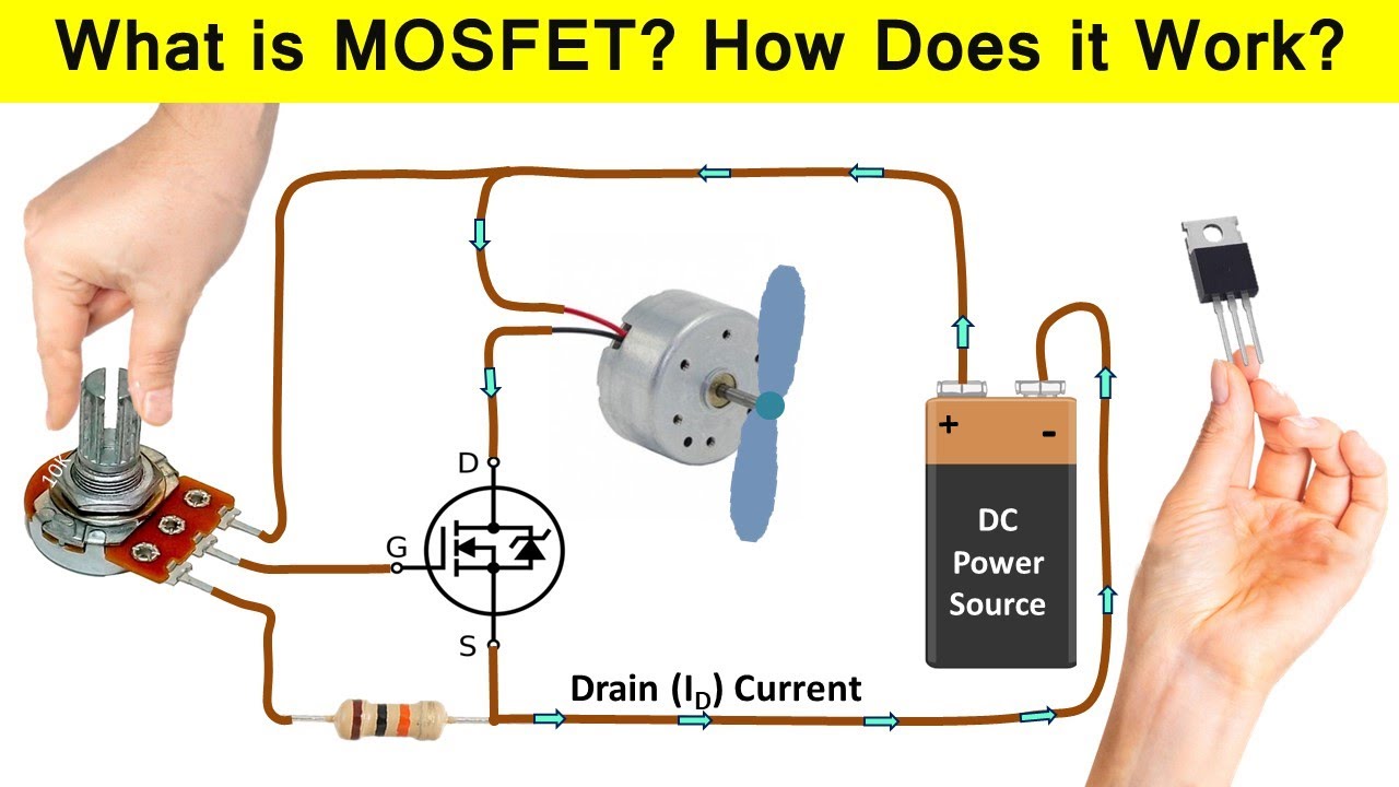
So, I heard about MOSFETs. Someone mentioned they act like super-fast, electronically controlled switches. Sounded perfect. I ordered a few, I think they were IRLB8721s or something similar? Honestly, just grabbed some recommended ones for beginners. When they arrived, they were just these tiny black plastic things with three metal legs. Simple enough, I thought.
First thing, I needed to figure out which leg did what. There’s usually a ‘Gate’, a ‘Drain’, and a ‘Source’. The names didn’t mean much to me at first. I just knew one leg was for the signal (telling it when to switch on/off), one was for the thing I wanted to power (the LEDs), and one connected to the ground or negative side of the power supply.
Hooking It Up (Attempt 1)
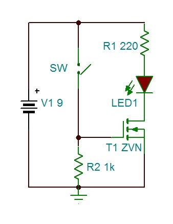
I grabbed my breadboard – you know, those white plastic boards with all the holes for sticking wires in. My plan was:
- Connect the LED strip’s negative wire to the MOSFET’s middle pin (which I guessed was the Drain).
- Connect the MOSFET’s rightmost pin (guessed Source) to the ground of my power supply.
- Connect the LED strip’s positive wire directly to the positive side of the power supply.
- Connect the MOSFET’s leftmost pin (guessed Gate) to a signal pin on my little controller board.
- Connect the controller board’s ground and the power supply’s ground together. This is important, I learned that the hard way later!
I wrote some simple code on my controller just to turn the signal pin on and off. Uploaded it. Plugged everything in. Nothing. The LEDs stayed stubbornly off. Okay, maybe I mixed up the pins?
Figuring Things Out
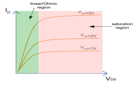
I double-checked the little drawing that came with the MOSFETs… nope, datasheet, that’s what they call it. Found a diagram online showing the pins for the specific type I had. Ah! I had the Drain and Source pins right, but the Gate needed a little extra help. Apparently, just connecting the signal wasn’t always enough. I needed a resistor, a small one, like 10k Ohms, connecting the Gate pin to ground. They call this a ‘pull-down’ resistor. It helps make sure the MOSFET turns off properly when the signal is low and stops it from floating around weirdly.
Wire Swap Time! So I carefully moved the wires around on the breadboard. Added that little resistor between the Gate pin and the ground rail on the breadboard. Made sure the main power supply ground and the controller board ground were definitely connected together.
Success!
Took a deep breath, plugged it all back in again. Ran the code. And boom! The LEDs flashed on, nice and bright! Sent the ‘off’ signal, and they shut off completely. It worked! This little three-legged thing was switching a decent amount of power based on a tiny signal from my controller board.
It felt pretty good, honestly. Going from “what’s this thing?” to actually making it control something. It wasn’t super complicated once I saw it working, but there were definitely a few small steps, like that resistor and grounding, that tripped me up at first. Definitely keeping these MOSFETs handy for future projects where I need to switch bigger loads.