So, I was trying to get this other project to work, you know? Needed to switch something on the “high side,” meaning I had to put the switch between the positive power supply and the load. Sounds simple, but man, it can be a pain sometimes. I’d been wrestling with N-channel MOSFETs for this, trying to get the gate voltage high enough, messing with charge pumps or special driver ICs. It was just becoming a whole thing, way more complicated than it needed to be. Honestly, felt like I was trying to build a spaceship just to turn on a light.
That whole setup was getting messy, a real rat’s nest of wires and components that I knew was just asking for trouble. I remember one time, with a previous attempt, things got so out of hand the whole board just gave up on me. Smoke and disappointment, the usual. It was one of those moments where you just want to throw your hands up and go watch TV. But, well, I needed this thing to work.
My P-Channel Adventure
Then I remembered I had a bunch of P-channel MOSFETs sitting in a drawer. I always forget about them because everyone talks about N-channels. But for high-side switching, especially when you’re controlling it with a lower voltage signal, like from a microcontroller, P-channels can be way easier. So, I thought, “Okay, let’s give this a shot.”
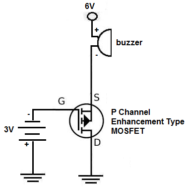
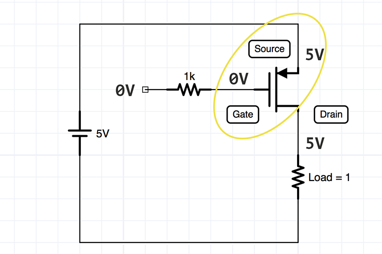
First, I grabbed one, an IRF9530 I think it was, but any similar P-channel would do the trick for what I was doing. The main thing with P-channels is they turn ON when their gate is pulled LOW relative to their source (which is usually connected to the positive supply). They turn OFF when the gate is at the same voltage as the source, or close to it.
So, here’s what I did, step-by-step, trying to keep it simple:
- Connected the Source: I hooked up the P-MOSFET’s source pin to my positive supply rail. Let’s say it was 12V for this project.
- Connected the Load: The thing I wanted to switch (a small motor, in this case) went between the P-MOSFET’s drain pin and ground (0V).
- The Gate – Pull-Up Resistor: This is important. I put a resistor, maybe a 10k ohm one, between the P-MOSFET’s gate and its source (so, between gate and 12V). This resistor keeps the gate pulled HIGH by default, making sure the MOSFET is OFF when I’m not actively trying to turn it ON. Without it, the gate can float, and the MOSFET might turn on randomly. No good.
- Controlling the Gate: Now, to turn the P-MOSFET ON, I needed to pull its gate LOW. My microcontroller outputs 0V for LOW and 5V for HIGH. Directly connecting a 5V microcontroller to pull a 12V gate down isn’t ideal and might not even work properly or could damage things. So, I used a small NPN transistor (like a 2N2222 or BC547) as a simple switch to pull the P-MOSFET’s gate to ground.
- The NPN’s collector went to the P-MOSFET’s gate.
- The NPN’s emitter went to ground (0V).
- The NPN’s base was connected to my microcontroller’s output pin through a current-limiting resistor (like 1k ohm, to protect the microcontroller pin).
How it worked: When my microcontroller sent a HIGH signal (5V) to the NPN’s base, the NPN transistor turned ON. This connected the P-MOSFET’s gate to ground through the NPN. So, the gate went LOW, and the P-MOSFET turned ON, letting current flow from the 12V supply, through the MOSFET, to my motor. The motor whirred to life!
When the microcontroller sent a LOW signal (0V) to the NPN’s base, the NPN turned OFF. Now, that pull-up resistor I mentioned earlier did its job. It pulled the P-MOSFET’s gate back up to 12V. With the gate HIGH, the P-MOSFET turned OFF, and the motor stopped. Simple as that.
Honestly, after all the headaches with other methods, seeing this work so cleanly was a relief. It felt like I’d found a secret shortcut. It’s not always the perfect solution for every single situation, but for a lot of my hobby projects where I need to switch a load on the high side with a microcontroller, this P-channel setup with an NPN to drive it has become my go-to. Way less fuss. Sometimes the old, simple ways are still the best, you know?