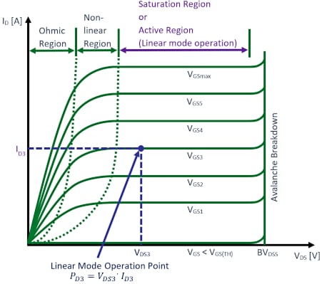
Okay, let’s get into this MOSFET linear region thing. I gotta tell ya, I thought I knew MOSFETs before, mostly how they act like a simple switch – totally ON or totally OFF. But then I heard people talk about using them in this ‘linear region’, kinda like a dimmer switch for electricity? That sounded wild, so I decided to actually poke around with some parts and see it for myself.

Digging Out the Old Gear
First thing I did was rummage through my trusty bin of electronics junk. Found a spare MOSFET – one of those common N-channel types, nothing fancy. Grabbed my old power supply unit, a simple variable voltage one. Then I gathered a breadboard, a bunch of jumper wires, resistors (a small one and a bigger one), and a multimeter I swear I gotta calibrate someday. Oh, and a little LED, just for quick visual feedback. Wanted to keep it dead simple.
Building the Basic Setup
Started hooking everything up like the MOSFET was just gonna be a switch. Plopped the MOSFET into the breadboard. Connected the power supply positive to the ‘top’ of my bigger resistor. Connected the other end of that big resistor to the MOSFET’s drain pin. Then I linked the MOSFET’s source pin straight back to the power supply negative. Drain to resistor, source to ground. Got it. Then I slapped the LED in parallel with the big resistor, just to see when power was flowing across it.
- Power Supply + —-> Resistor (big one) —-> MOSFET Drain
- MOSFET Source —-> Power Supply –
- LED + —-> Between Resistor & Drain
- LED – —-> MOSFET Source
Where’s the Linear Part?
Right, so the tricky part is controlling the gate. The gate voltage tells the MOSFET how much to open up. Powered up the drain circuit with maybe 10 volts. I touched a wire from the gate straight to the positive rail. Boom! LED lit up bright, MOSFET felt warm – classic full ON switch mode. Voltage across the MOSFET drain and source? Almost zero. Like a closed circuit.
Then, I disconnected the gate. LED off, MOSFET cold. Blocking all current, like an open switch. Easy. But how do I make it partially open?
Getting Tricky with Gate Voltage
Here’s where the fun began. Instead of jamming the gate straight to the power, I grabbed that variable power supply channel for the gate. Connected its positive to the MOSFET gate, negative to the MOSFET source (and the main power negative). Now I can dial in exactly how much voltage I’m shoving into the gate.

First, I turned up the drain voltage to like 5V. Left the gate voltage at zero. Multimeter across drain-source showed… 5V! LED off, no current flowing. Blocked.
Started slowly turning up the gate voltage. Past 1 volt… nothing. Past 2 volts… still nada. Then around 2.5V to 3V something happened! The LED started to glow. Just a little. Barely visible. Measured the drain-source voltage. Instead of 5V or 0V… it was maybe 4.5V! Holy cow! That meant voltage was actually being dropped across the MOSFET itself.
Turned the gate voltage up a bit more. LED got brighter. Drain-source voltage dropped a bit more, maybe down to 4V. Kept going. As I increased the gate voltage, the drain-source voltage kept decreasing. The current through the LED increased smoothly. This was it! The MOSFET wasn’t a hard switch here. It was resisting the flow, acting like a variable resistor controlled by the gate tap!
Lightbulb Moment & Essential Facts
So here’s the core realization:
- Gate voltage needs to be high enough to crack the MOSFET open a bit. That “cracking point” is the threshold voltage.
- Once open a little, drain current starts flowing. But crucially, if the voltage difference between drain and source (drain-source voltage) is still relatively large, the MOSFET is in this weird in-between state.
- In this state, the MOSFET acts like a resistor. The value of that ‘resistance’ is controlled by the gate voltage! Higher gate voltage makes it act like a smaller resistor.
- The power dissipation happens inside the MOSFET. This is key! That voltage drop across drain-source multiplied by the current flowing? That’s heat generated right in the MOSFET. Mine got warm fast even at low currents!
The Struggle is Real (Smoke-Free)
Man, getting smooth control was fiddly. Small changes on the gate voltage knob made big differences at first. My fingers shook a little. I accidentally cranked the gate voltage way up while the drain voltage was also high – current spiked, MOSFET got noticeably warm, LED almost blinded me. Quickly backed it off. Hands sweating! This linear region isn’t efficient; it dumps power as heat.

The other thing? Just turning up the gate voltage enough doesn’t guarantee linear mode. If I set the drain voltage super low first (like 1V), then turned up the gate voltage, the MOSFET would slam straight into full ON mode much easier, barely spending any time ‘resisting’. Like jumping from OFF to ON with barely any in-between. The drain-source voltage has to be significant enough relative to the gate voltage for that nice resistive behavior to kick in properly.
Wrapping It Up
Yeah, so that’s basically the hands-on mess I went through. MOSFET linear region? It’s like barely cracking open a powerful water valve against high pressure. You get flow, but the valve fights back and gets hot doing it. It’s real, I saw it happen on my breadboard – the smoothly changing drain-source voltage proved it. But dang, these little chips can get grumpy quick if you push too much power through them while they’re only partly open! Handle with care. They just wanna be full-on switches and chill, or be totally off and lazy. This halfway work makes ’em sweat.

