So I saw this MOSFET AND gate nonsense online and thought, heck, let’s actually build the thing instead of just staring at diagrams. Grabbed my dusty parts bin and started digging.

Okay first, gathering parts
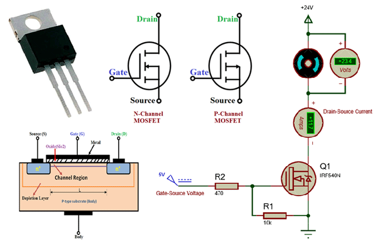
Figured I needed a couple of N-channel MOSFETs. Found these old IRF540N ones buried under some jumper wires – good enough for a quick test. Then grabbed:
- A breadboard (obviously)
- My reliable 5V power supply
- Two push buttons for inputs (A and B)
- Two LEDs, one for each input, one for the output
- A bunch of resistors – 1kΩ for the LEDs and pull-downs, 10kΩ for pulling the MOSFET gates low
- Jumper wires galore – it always looks like a spiderweb
Time to wire this circus up
Followed the basic AND gate setup with two MOSFETs:
- Stuck the first MOSFET on the breadboard. Called it Q1.
- Plugged the second MOSFET (Q2) right next to it. Its source? Straight into Q1’s drain. Felt a bit like stacking bricks.
- Connected Q1’s source straight down to Ground. That cold, reliable ground.
- Took the output pin right after Q2’s drain. Ran a wire to Ground with a 1kΩ resistor acting like a pull-down guard. Then popped the output LED right there, with its own resistor to keep it safe.
- Now the inputs. For input A, I hooked a wire to Q1’s gate. Added a 10kΩ resistor dragging that gate nice and low to Ground. Then wired one push button between this gate point and the +5V rail. Push the button? Boom, A goes high! Stuck an LED here too.
- Input B went to Q2’s gate. Did the exact same thing: 10kΩ pull-down to Ground, push button to +5V, input LED. Symmetry feels good.
- Finally, dragged Q2’s source pin? Not to ground. Straight into Q1’s drain. That’s the key connection.
The moment of truth (and panic)
Plugged in the power supply, holding my breath. The input LEDs looked dead. Good, buttons weren’t pressed.
Test 1: Pressed ONLY button A. Saw the input A LED light up bright. BUT the output LED? Dead dark. Okay, working as expected for A=HIGH, B=LOW.
Test 2: Released A, pressed ONLY button B. Input B LED lit up happy. Output? Still off. Sweet. A=LOW, B=HIGH = Output LOW.
Test 3: Pushed nothing. Both input LEDs off? Output stayed dark like a cave. Both LOW = Output LOW. Cool.
Test 4: Deep breath. Pressed BOTH buttons A AND B. Saw both input LEDs glow. Checked the output… it lit up! Solid green light. A=HIGH, B=HIGH = Output HIGH!
Honestly, was kinda expecting smoke. But nah, it just worked. Makes sense when you think about it: Only when BOTH MOSFETs get the HIGH signal on their gates (turning them both ON) can the juice flow cleanly from the output point all the way through Q2’s drain-to-source, then through Q1’s drain-to-source, straight down into Ground. That pull-down resistor gets overpowered and the output LED shines.
Final thought? It felt way more real building it than reading about it. Seeing that output LED glow ONLY when both buttons are down is just… satisfying. Proof that we’re all just messing around with electricity gates until stuff lights up.