Okay, so P-channel MOSFETs. Man, the first time I really had to get my hands dirty with one of these for a project, it felt a bit like I was trying to write with my left hand, you know? I was so used to N-channel MOSFETs, where you just feed a positive voltage to the gate and boom, it switches on.
I remember I was fiddling with a board where I needed to switch power on the high side of a circuit. Basically, the gadget I wanted to power up was connected to the positive supply rail, and I needed a way to turn its connection to that positive rail on and off. My first instinct, coming from N-channel land, was to try and use an N-channel there, putting it between the positive supply and my gadget. That, as you can imagine, didn’t go too smoothly. To really turn an N-channel ON in that spot, its gate voltage needs to be significantly higher than the source, which was already at my main supply voltage. Not exactly easy to do without adding a whole bunch of extra components like a charge pump or something.
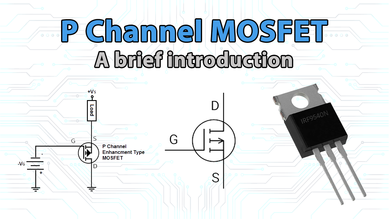
So, that’s when I properly dug into P-channel MOSFETs. I think I grabbed something like an IRF9540, or a similar common part I had lying around in my bits box. I glanced at the datasheet, but honestly, those things can sometimes just give you a headache with all the graphs and specs before you’ve even tried to make the thing work.
Here’s pretty much the process I went through to get it to behave:
- First, I connected the Source pin of the P-MOSFET straight to my positive power supply. Let’s say it was a +12V supply for this example.
- Then, the Drain pin, that went to one end of the thing I wanted to power – I think it was a small LED array at the time.
- The other end of my LED array was connected to Ground. Simple enough.
- Now, the Gate. This was the part where I had to scratch my head a bit and experiment.
I quickly found out that to get the P-MOSFET to switch ON, I had to pull its gate voltage lower than its source voltage. And not just a tiny bit lower, but by a decent amount, enough to overcome its gate-source threshold voltage, which, for P-channels, is a negative number. So, if my source was sitting at +12V, I had to drag the gate down to, say, 0V (ground) or even just a few volts if the threshold was low enough.
So, when I connected the gate to my microcontroller’s output pin and set that pin to LOW (0V), the P-MOSFET’s gate was at 0V. Its source was at +12V. That created a gate-to-source voltage (Vgs) of 0V – 12V = -12V. This was plenty to turn it fully ON, and current started flowing from the source, through the MOSFET, to the drain, lighting up my LEDs!
To turn the P-MOSFET OFF, I needed to do the opposite. I had to make the gate voltage pretty much the same as the source voltage. So, if the source is at +12V, the gate needs to be at +12V, or very, very close to it. This was a bit of a trap. If I was using a 5V microcontroller, and I set its output pin HIGH (to +5V), the Vgs would be 5V – 12V = -7V. For some P-MOSFETs, -7V might still be enough to keep them partially or even fully on! That was a real “aha!” moment of frustration. I realized I absolutely had to make sure the gate was pulled all the way up to the source voltage to guarantee it was completely off.
So, my go-to little circuit for driving a P-MOSFET gate from a lower voltage microcontroller (like 5V controlling a 12V P-MOSFET) usually ended up looking like this:
- I’d put a pull-up resistor between the P-MOSFET’s gate and its source (so, gate to +12V in my example). This resistor makes sure the MOSFET is normally OFF.
- Then, I used a small NPN bipolar transistor, something like a 2N2222 or BC547. The microcontroller’s 5V output would go to the base of this NPN (through a base resistor, of course). The NPN’s emitter would go to ground, and its collector would connect to the P-MOSFET’s gate.
- When the micro output went HIGH, it turned the NPN ON. The NPN would then pull the P-MOSFET’s gate down towards ground, overcoming the pull-up resistor and turning the P-MOSFET ON. When the micro output went LOW, the NPN turned OFF, and the pull-up resistor would pull the P-MOSFET’s gate back up to +12V, turning it OFF.
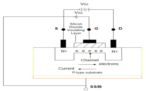
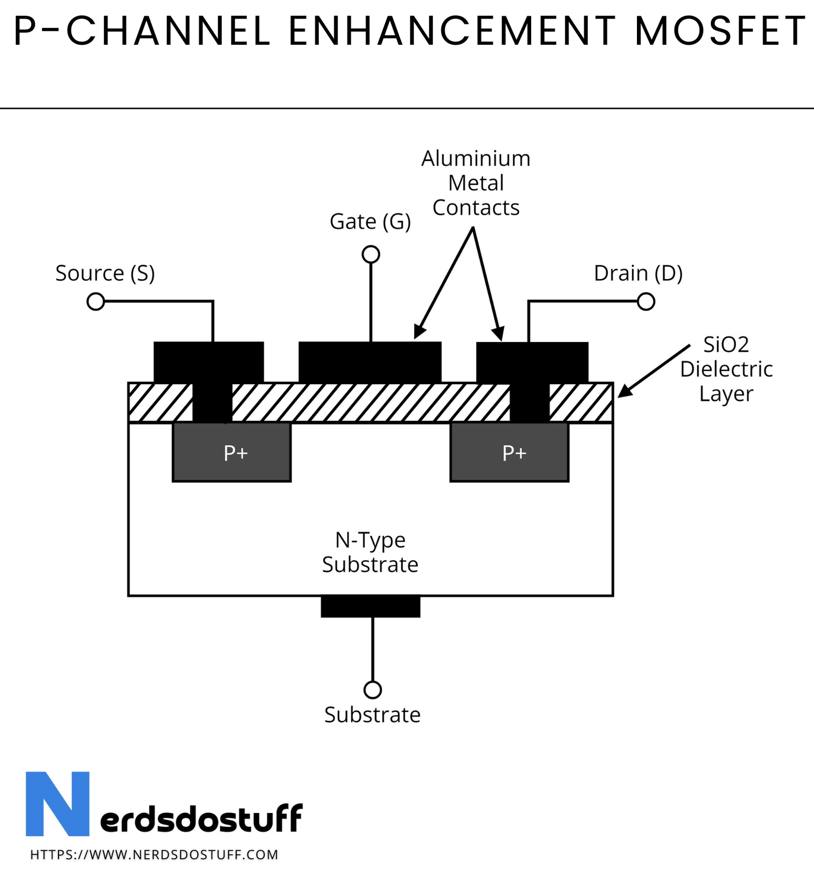
It’s like, with an N-channel, you apply a positive voltage (relative to its source) to the gate to open the path. With a P-channel, you need to make the gate voltage negative (again, relative to its source) to open the path. I read somewhere that when you apply that lower voltage to the gate of a P-MOSFET, the N-type material just under the gate sort of flips and becomes P-type, creating a channel. This lets current flow from the P-type source, through this newly formed P-type channel, to the P-type drain. It’s all P-P-P when it’s conducting.
One thing that used to confuse me was the whole “negative voltage” talk. It doesn’t always mean you need a power supply that’s spitting out -5V or -12V. It’s all about the voltage difference between the gate and the source (Vgs). If your source is at +5V and you pull the gate to 0V, your Vgs is -5V, and the P-MOSFET turns on. If your source is at +12V and you manage to pull the gate to +7V, your Vgs is still -5V. It’s that difference that matters.
So yeah, P-channel MOSFETs. They felt a bit weird to me at first, especially after getting comfortable with N-channels. But they are super handy, especially for that high-side switching stuff. Once I really got it into my head that “pull the gate down to turn it on” and “make sure the gate goes all the way up to the source voltage to turn it off,” things started to click. I definitely let the magic smoke out of a few components in my early days, or had circuits that just wouldn’t turn off properly, all because I hadn’t quite nailed the gate drive for these P-channel fellas. Learning experience, for sure!