Alright, so I decided to mess around with a MOSFET Common Source amplifier the other day. Been meaning to build a simple one for ages, just to refresh my memory and see if I could still get one working right off the bat.
Getting Started – The Parts Bin Dive
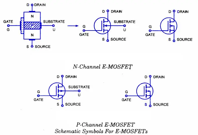
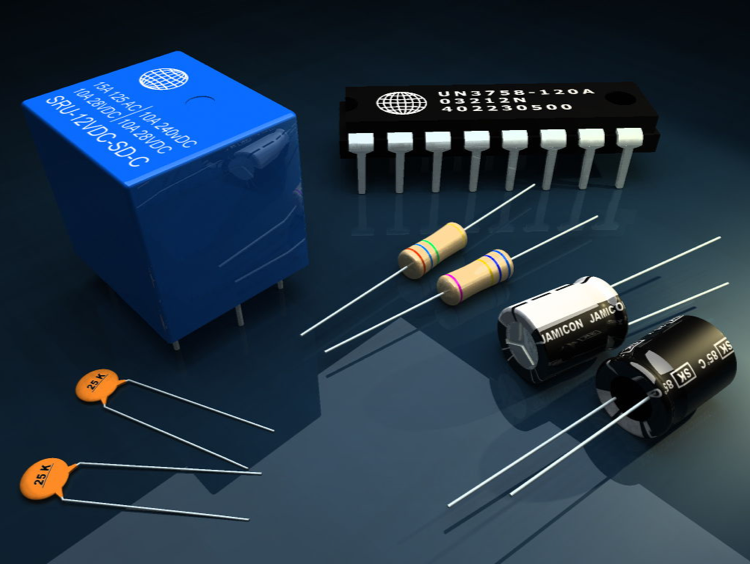
First thing, naturally, was digging through my component drawers. Needed the star of the show, a MOSFET. Found a bunch of old 2N7000s, perfect for this kind of low-power messing around. Grabbed some resistors – a mix of values because I wasn’t sure exactly what I’d need for biasing yet. Also snagged a few capacitors for coupling and bypass, maybe some 0.1uF and 10uF ones. Power supply, signal generator, and my trusty oscilloscope were already on the bench.
Sketching and Biasing – The Head Scratching Part
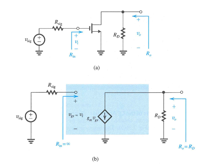
I sketched out the basic CS configuration on a notepad. You know the one: resistor on the drain (Rd), resistor on the source (Rs) sometimes for stability, and a voltage divider (R1, R2) to bias the gate. This is where the guesswork started.
Getting that gate bias voltage right is key. You want the MOSFET sitting nicely in its active region. I started with some values I vaguely remembered:
- Maybe 10k for Rd?
- Tried a small Rs, like 1k.
- For the R1/R2 divider, maybe shoot for a gate voltage a bit above the threshold voltage of the 2N7000. Picked 100k for R1 and R2 initially, aiming for roughly half the supply voltage (I was using 9V).
Needed coupling caps (C1, C2) to block DC from the input signal and the output load, and a bypass cap (Cs) across Rs if I wanted maximum gain (I decided to add this later if needed).
Putting it on the Breadboard
Okay, time to actually build this thing. Stuck the 2N7000 into the breadboard. Carefully placed the resistors – Rd from drain to +9V, Rs from source to ground, R1 from +9V to gate, R2 from gate to ground. Added the input capacitor to the gate and the output capacitor from the drain. It looked messy, wires everywhere, standard breadboard stuff.
Double-checked all connections. It’s super easy to stick a wire in the wrong hole, especially late at night.
Power Up and Testing – The Moment of Truth
Connected the 9V supply. No smoke, good start. Hooked up the signal generator to the input capacitor, set it to a small sine wave, maybe 1kHz and 50mV amplitude. Connected the oscilloscope probe to the output capacitor.
And… well, it sort of worked. I saw an output signal, and it was definitely bigger than the input, and importantly, it was inverted (180 degrees out of phase), which is what you expect from a CS amp. Success!
Fiddling and Fine-Tuning
The gain wasn’t amazing though, and the waveform looked a bit squashed on one side (clipping). This usually means the bias point isn’t quite right. The MOSFET was probably hitting saturation or cutoff too early.
So, I started fiddling. Changed R1 and R2 values a bit to adjust the gate voltage. Swapped Rd for a different value to change the gain and output swing room. If I made Rd too large, the output clipped badly on the positive swing. Too small, and the gain dropped. It took a bit of trial and error, swapping resistors in and out, watching the scope.
I also tried adding the bypass capacitor across Rs. That definitely boosted the AC gain, as expected, because it shorts out Rs for the AC signal. But sometimes that can make things less stable, depends what you need.
Final Thoughts
After some tweaking, I got a reasonably clean, amplified sine wave on the scope. Gain was probably around 5-10, nothing crazy but definitely amplifying. It was good fun, reminded me how sensitive biasing can be. It’s one thing to see the circuit in a book, quite another to actually build it and see how changing one resistor value affects the output waveform right there on the screen. Definitely a worthwhile little project.