So last night I was messing around with this MOSFET on my workbench, right? Tried making a simple circuit to switch a motor on and off. Followed one of those basic diagrams online. Plugged it in, turned it on… nothing. Motor wouldn’t budge. Checked connections twice. All seemed fine.
What Went Weird?
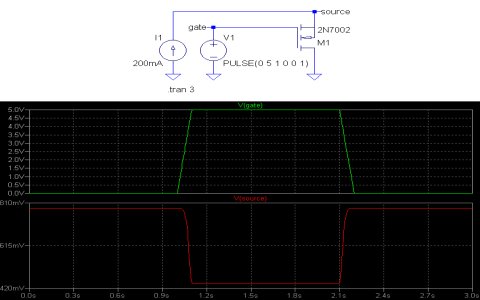
Got annoyed. Decided to test the MOSFET alone. Grabbed my multimeter. Did the usual diode test thing between the Drain and Source pins. Shocker! It showed a voltage drop! Like a regular diode would. My brain froze. “Hold up,” I thought. “Isn’t a MOSFET supposed to be a switch? Like, current flows one way when it’s on, blocks completely when off? Why’s there a diode here?” Figured maybe I got a faulty part. Happens.
The “Duh” Datasheet Dive
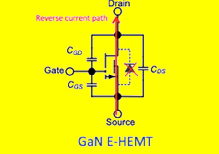
Sigh. Pulled up the datasheet for this specific MOSFET. Scrolled past the specs, flipped to the internal structure diagram. Boom. Right there, inside the little schematic drawing. There it was – a diode symbol, drawn right between the Drain and the Source! Plain as day. Always there. Why didn’t I notice this before?
It’s called the “body diode.” Turns out it’s just built-in. Not a defect. Not an afterthought. Part of how these things are made. Blew my mind. Felt kinda stupid for missing this basic fact for months.
Why This Matters More Than I Thought
- The Sneaky Shortcut:
- My Motor Murder Mistake:
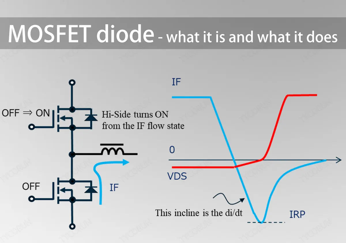
- Forgetting the Freewheel Path:
- It’s slow. Really slow to react.
- It can’t handle much power.
- Doing this is basically asking your MOSFET to commit suicide slowly.
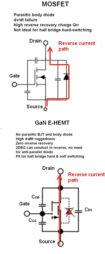
That diode only lets current flow one way: from Source to Drain. Not the other way! If your circuit tries to push current backwards when the MOSFET is off… bam. That diode will happily conduct. Ruins your nice blocking action. Short circuit city!
That motor I tried to control? When you turn off power to a spinning motor thing, it can generate a spike of voltage in the opposite direction. Backwards current! Guess what? When my MOSFET turned off, that body diode acted like a free pass for that backward spike. Maybe damaged my poor MOSFET. Couldn’t control the motor properly. Explains why everything felt sluggish or just died.
In DC motor circuits or where you control inductive loads (stuff like relays, coils), you absolutely need a safe path for that backward spike to go. Usually, you add an external diode for this job. But here’s the kicker: if you only rely on the MOSFET’s internal body diode to handle that spike? Bad news. Why?
The Fixes I Finally Understood
So, how do we avoid frying the poor MOSFET or having weird circuit fails?
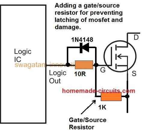
- External Diode is King:
- For AC Circuits:
For switching motors or inductive loads? ALWAYS add that external diode. Choose a fast recovery one. Connect it close to the load, cathode pointing towards the positive supply. This gives the backward spike a safe, fast detour right around the load itself. Protects the MOSFET entirely.
Working with AC? Need to block current in both directions reliably when the switch is off? Forget relying on a single MOSFET. Its body diode ruins that plan. You need a back-to-back pair of MOSFETs facing opposite ways. Traps that pesky body diode inside so it can’t conduct accidentally. Game changer.
Honestly, spending hours debugging my little motor driver only to find out the problem was built into the darn part? Maddening. But learning about this sneaky diode, why it exists, and how to work around its quirks? Pure gold. Makes my circuits actually behave like I expect them to. Don’t sleep on that little body diode hiding inside every MOSFET!