Alright, so today I’m gonna walk you through this common source MOSFET amplifier thing I messed around with. Nothing too crazy, just a simple setup, but hey, gotta start somewhere, right?
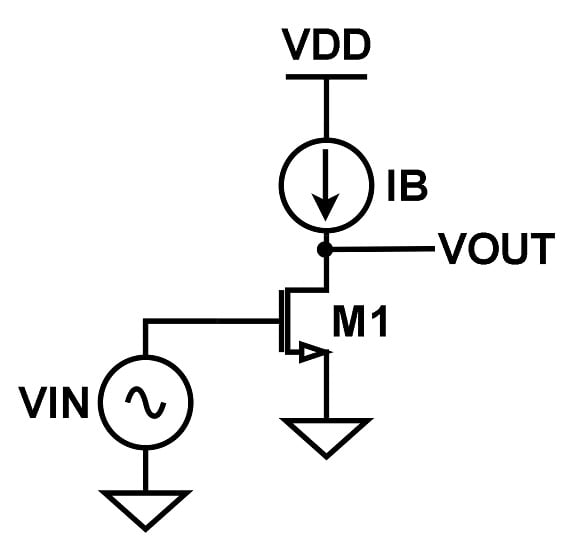
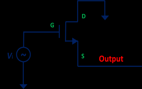
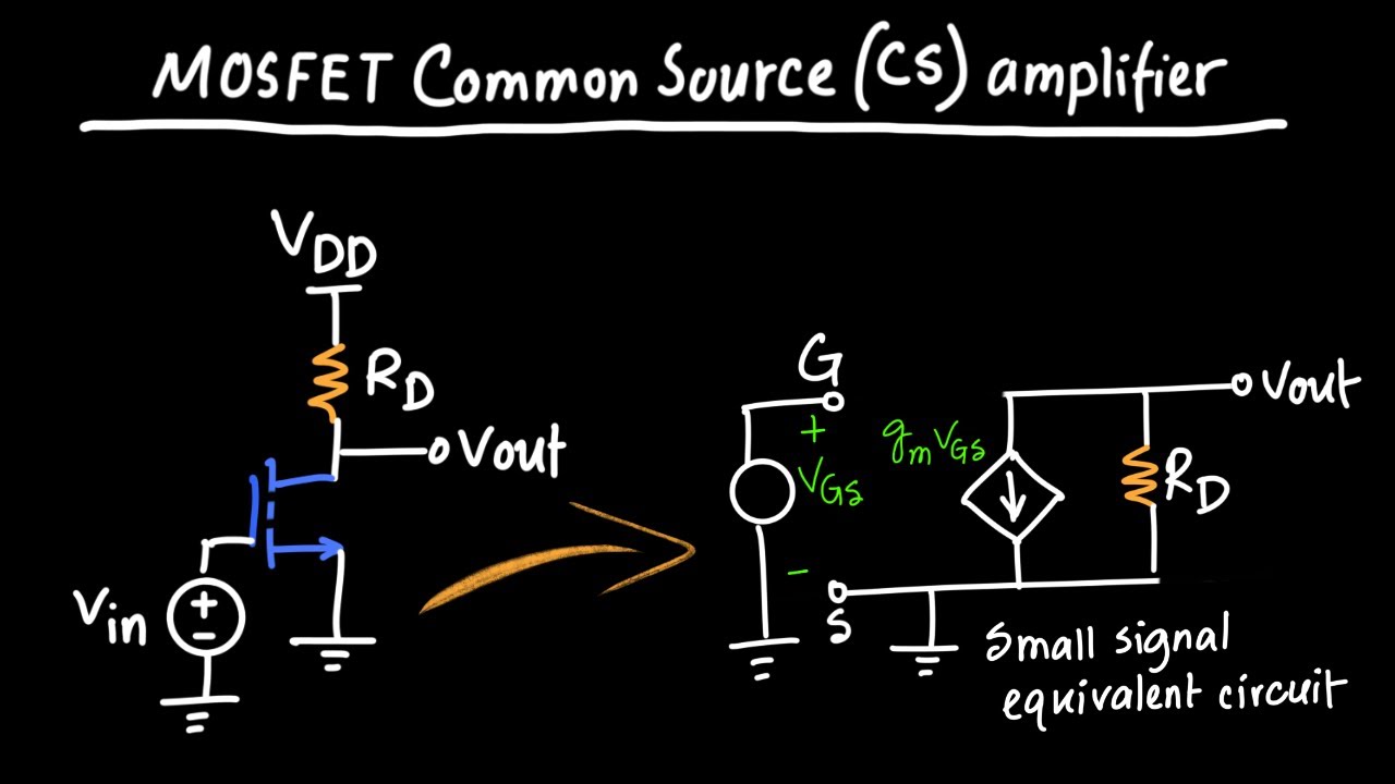
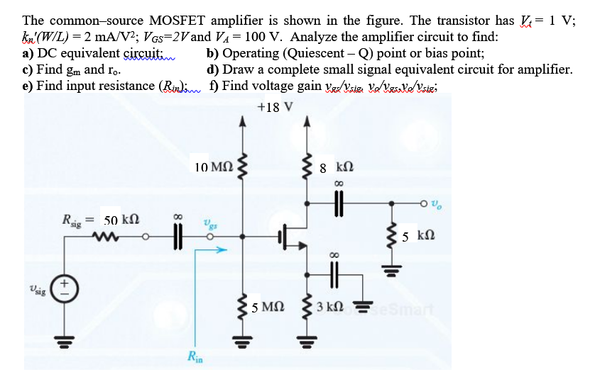
First off, I was looking at the basic circuit diagram online. You know, the one with the MOSFET, a couple of resistors for biasing, and a capacitor to block the DC. I thought, “Yeah, looks easy enough.” Famous last words, I tell ya.
So, I grabbed my breadboard, a 2N7000 MOSFET (because that’s what I had lying around), some resistors (10k and 1k, following the example circuit), a 0.1uF capacitor, and a signal generator. The goal was to amplify a small signal, hopefully without blowing anything up.
I started by setting up the biasing network. That’s the part with the resistors that sets the gate voltage. I double-checked my resistor values with my multimeter, because you never know if you grabbed the wrong one. I wired it up on the breadboard, making sure everything was connected properly. Breadboards can be finicky little things, trust me.
Then came the MOSFET. I carefully plugged it in, making sure the pins were in the right slots. Drain, gate, source – gotta get those right. I connected the drain to the power supply (9V in this case) through a resistor, and the source to ground. That’s the basic setup.
Next, I added the capacitor to the input signal line, to block any DC offset from my signal generator. I hooked up the signal generator to the input and the oscilloscope to the output. I started with a small sine wave, like 100mV at 1kHz.
And… nothing. Well, not exactly nothing, but the output was just a tiny, distorted version of the input. It was barely amplified at all. I was expecting a much bigger signal. Time to troubleshoot.
First thing I checked was the bias voltage on the gate. I used my multimeter to measure the voltage at the gate pin. It was lower than I expected. Turns out, my resistor values weren’t quite right for the MOSFET I was using. I swapped out one of the resistors to get the gate voltage closer to what I wanted, around half the supply voltage.
That helped a bit, but the signal was still distorted. I started playing around with the input signal amplitude and frequency. I noticed that the distortion got worse at higher frequencies. I figured it might be the capacitor, so I tried a different value. No real improvement.
Then I remembered something about MOSFETs: they’re sensitive to temperature. I touched the MOSFET (carefully!) and it felt a little warm. Maybe it was overheating and affecting the signal. I didn’t have a heatsink handy, but I decided to try reducing the supply voltage. I dropped it down to 5V.
And that actually made a difference! The signal was cleaner and the amplification was better. It wasn’t perfect, but it was a noticeable improvement. I played around with the resistor values a bit more, tweaking them to get the best amplification I could without too much distortion.
Finally, I got a decent signal amplification. It wasn’t a huge gain, maybe around 5x or so, but it was definitely amplifying the input signal. The distortion was still there, but it was much less noticeable.
What I learned:
- MOSFET biasing is tricky. You gotta get the gate voltage just right for your specific MOSFET.
- Temperature matters. MOSFETs can overheat and affect the signal.
- Component values are important. Experimenting with different resistor and capacitor values can make a big difference.
Overall, it was a fun little project. I learned a lot about MOSFET amplifiers, and I got a decent signal amplification in the end. It’s not going to win any awards, but it was a good learning experience.
Next time, I think I’ll try adding a feedback resistor to improve the stability and reduce the distortion. But for now, I’m happy with my little common source amplifier.