Okay, so I had this project where I needed to use a MOSFET, but I was totally confused about the pin layout. I mean, I knew what a MOSFET was supposed to do – act like a switch, you know? – but figuring out which pin was which? That was a whole other story.

First thing I did was grab the datasheet. I mean, that’s what you’re supposed to do, right? But honestly, sometimes those things are written in, like, ancient hieroglyphs. All those tiny diagrams and technical jargon… it made my head spin. I spent a good hour just staring at it, feeling more confused than when I started.
Then, I thought, “Okay, maybe the internet can help.” I went on a searching binge. I looked at so many websites, forum posts, and even some videos. Some of them were helpful, kind of, but a lot of them just showed different types of MOSFETs, and I didn’t know all the terms. It was information overload!
I was getting pretty frustrated at this point. I even considered just randomly connecting wires and hoping for the best (don’t do that, by the way – I learned that lesson the hard way a few times!). But, I took a deep breath and decided to try a more hands-on approach.
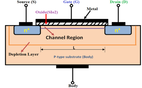
I grabbed my multimeter, the one with the continuity tester. That little beeping sound is a lifesaver! I knew, from my searching, that the gate pin is usually isolated, so it shouldn’t have continuity with the other two pins. So, I started poking around.
I put one probe on one pin and then touched the other probe to the other pins, one at a time. I found two pins to start out with that had my multimeter go off, so I knew right away that my third pin was the gate.
Here’s the basic process I followed:
- Set the Multimeter for continuity
- Test all pin combinations until there is no continuity.
- The pin that showed no continuity to the others had to be the gate!
- Then, I could find the source and drain.
Figuring out the source and drain was a bit trickier. I remembered something about the body diode inside the MOSFET, and how it only conducts in one direction. So, I switched my multimeter to diode mode and tested the remaining two pins. I found that one way, I got a reading (around 0.5V or so), and the other way, I got nothing.
The Result
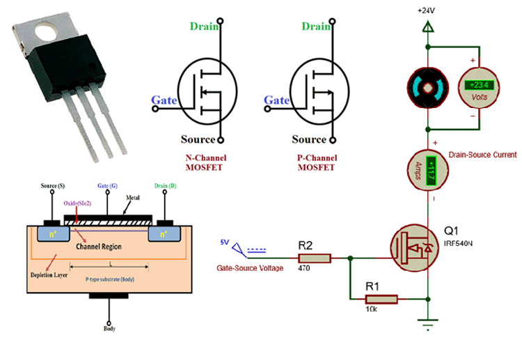
Boom! I had my pinout. It turned out the MOSFET was using the standard setup.
It took me a while, and I definitely learned a lot along the way. The biggest lesson? Don’t be afraid to get your hands dirty and experiment (safely, of course!). Datasheets are important, but sometimes, you just gotta grab your tools and figure things out yourself.