Alright, so today I’m gonna ramble about something I messed with recently: CMOS versus MOSFET. It’s not like I’m some expert, but I figured I’d share what I learned from actually getting my hands dirty.
It all started when I was trying to build this simple little circuit for a project. I needed a switch, and, like a dummy, I wasn’t really thinking about power consumption. I just grabbed a MOSFET I had lying around. Worked fine at first, but then I noticed the thing was getting kinda warm. That got me thinking about CMOS stuff that I’d kinda glossed over back in the day.
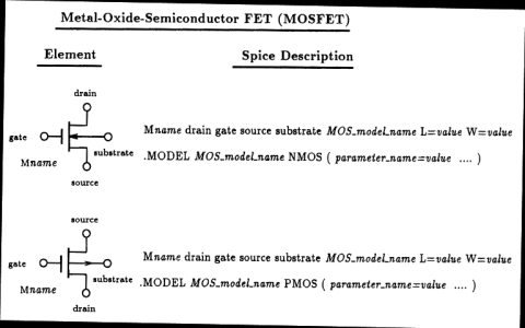
So, I started digging around. The big thing that smacked me in the face was the whole power dissipation deal. With a basic N-channel MOSFET, you’ve got that current path from Vdd to Vss whenever the transistor is on. That’s just wasted power, plain and simple. It’s like leaving a tap running all the time. And in my case it quickly made my circuit hot, and I needed to use a heat sink.
Then I looked at CMOS. The basic idea is that you use both an N-channel and a P-channel MOSFET together. The cool thing is, ideally, only one of them is switched on at a time. So you don’t have that constant current path from Vdd to Vss. Dynamic power when switching yeah, but way less static power. It’s like having a tap that only runs when you need it.
First thing I did was try simulating both setups. I used some online circuit simulator – nothing fancy. Just wanted to see the current draw. The difference was pretty stark. The single MOSFET was just chugging away power, even when it wasn’t actively switching. The CMOS setup was way more efficient. I was impressed.
Next, I decided to build a real-world example. I grabbed a couple of MOSFETs (one N-channel, one P-channel), a resistor, and some wires. I wired up a simple inverter circuit using the CMOS setup. Then I wired up the same circuit using just the N-channel MOSFET. I powered both from the same power source, about 5V.
The real kicker came when I measured the current draw with my multimeter. The MOSFET circuit was pulling milliamps constantly. The CMOS circuit? Microamps! Huge difference! You could literally feel the difference with your finger after it was running for a bit, the mosfet felt warm, and the cmos felt close to room temp.
I also noticed the noise immunity was better with the CMOS. Meaning that the input signal needed to be cleaner for the single mosfet circuit, or it would give out random outputs and act erratically. CMOS was a lot more forgiving and stable.
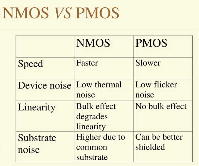
- CMOS: Low static power consumption, high noise immunity, more complex to design.
- MOSFET: Simpler design, higher static power consumption, lower noise immunity.
Look, I’m no expert. But messing around with this stuff myself really drove home the difference between CMOS and MOSFET. And it got me thinking more about power consumption in my projects. Now, depending on the situation, I would definitely pick CMOS for low power scenarios, and MOSFET for simpler, non-power sensitive projects.
So yeah, that’s my little CMOS vs. MOSFET adventure. Hope it helps someone out there, or at least makes you think a little bit about what’s going on under the hood!