So I had this sudden urge to actually get my hands dirty with some real hardware this afternoon. You know, actually remember what all this textbook transistor stuff feels like in practice. Started rummaging through my old electronics stash – total chaos, wires everywhere, dust bunnies the size of small rodents. Found a dusty breadboard, a handful of resistor packs, and my trusty, slightly beaten-up adjustable power supply hiding under a pile of old schematics.
First Up: The Old-School BJT
Grabbed a BC547 first, that classic little guy. Needed an LED to see it work. Slammed it onto the breadboard, hooked up a resistor to limit the LED current, and connected my power supply wires – positive to the resistor, other end to the LED’s leg, LED’s other leg to the BJT’s “collector” terminal. Then hooked a wire from the BJT’s “emitter” down to ground.
Now for the control magic. Used a tiny jumper wire to connect from another point on the power supply (set super low first!) to a current-limiting resistor, then hooked that resistor to the BJT’s “base” terminal. This base current is like whispering to the BJT – “Hey buddy, let some juice through.” Slowly nudged the base voltage up. Watched the LED like a hawk. Nothing… nothing… then a faint glooooow. Had to crank that base voltage way higher than I vaguely remembered to get the LED bright. Measured the voltage drop across the BJT itself when it was lit. Kinda high! Felt like it was drinking some power just sitting there turned on.
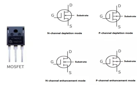
Switching Gears to the MOSFET
Okay, cleared a space and pulled out an IRFZ44N MOSFET. Bigger fella, needs heat sinking for real work, but just lighting an LED? Should be fine. Plugged it in differently. LED and its resistor went between the power supply positive and the MOSFET’s “drain” leg. Hooked the MOSFET’s “source” leg straight down to ground.
Now, instead of controlling the current into a base, I connected a new wire from my adjustable power supply directly to the MOSFET’s “gate” terminal. No resistor needed here? Strange! Slowly turned up this gate voltage from zero… zero… still zero… LED dead dark. Then, BAM! Around 3.5 volts or so, the LED suddenly blasted to full brightness like someone flipped a switch. It was dramatic! Measured the voltage drop across the MOSFET itself when on. Crazy low! It felt like a clean, tight connection.

The Lightbulb Moment (Literally!)
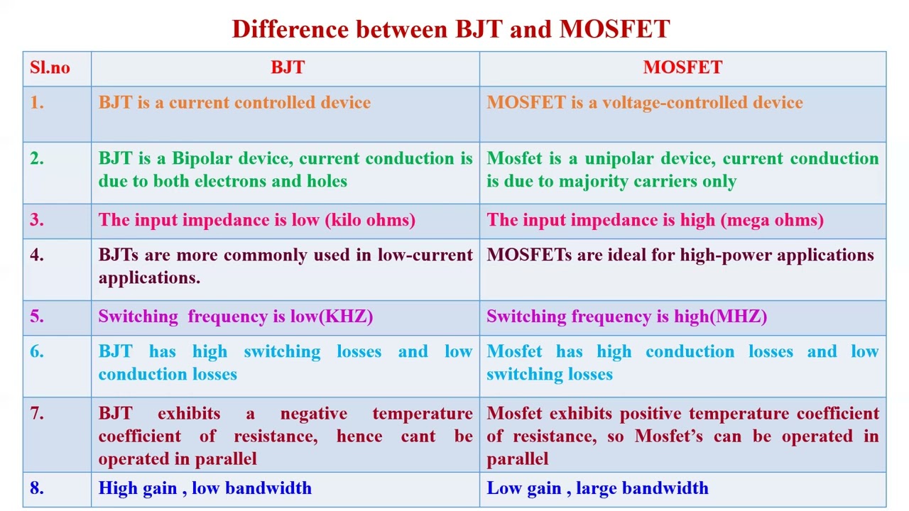
Sitting there blinking between the two circuits, the differences clicked:
- Triggering: BJT needs a trickle of current into the base, like filling a bucket to open a tap. MOSFET only wants voltage on the gate – almost no current at all. It’s like pressing a button.
- Turning On: BJT fades in slowly like a sunrise. MOSFET snaps on like a light switch clicking.
- Power Waste: When conducting lots of current (like the LED bright), the BJT was noticeably warm. Measured more voltage dropped across it = wasted power as heat. MOSFET stayed ice cold, voltage drop miniscule. Way more efficient for letting big currents flow.
- Control Feel: Controlling the BJT felt analog, fiddly with base voltages. The MOSFET felt absolutely digital – OFF or ON, no in-between mess.
It’s one thing to see curves in a book or formulas. Feeling the BJT slurp base current, seeing the voltage it wastes when on, then witnessing the MOSFET snap on instantly with almost no wasted juice? That sticks. Those graphs suddenly had meaning beyond squiggly lines. My breadboard looked like a rat king afterwards, but man, it was satisfying. Why did I do it? Because last semester I tried explaining this to a student using only textbook diagrams and theory, and the utter confusion on their face haunted me. You gotta poke it to get it.