How I Finally Got My Annoying MOSFET Bias Circuit Working
Okay folks, grab some coffee, because this one was a headache. I figured I’d share the absolute mess I went through trying to get this bias setup for a MOSFET to actually do its job. Spoiler: it felt impossible at first.

So there I was, super excited to finish this little amplifier project. Soldered everything up, followed the schematic I found online pretty carefully, or so I thought. Powered it on expecting sweet, sweet amplified sounds… and got absolutely nothing. Not a hiss, not a pop, just dead silence. Total gut punch after spending all that time. Coffee level already dangerously low.
First things first, I panicked. Obviously. Then I grabbed my trusty multimeter and started poking around like a complete amateur.
- Checked the power supply connections first: Okay, voltage’s good. Not the issue.
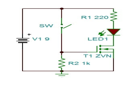
- Looked at the MOSFET pinout again: Yep, Source, Drain, Gate. Pretty basic, thought I got it right.
- Measured voltage at the Gate pin: Almost zero. That ain’t right. The whole point of the bias circuit is to give that Gate a little kick to turn the thing on properly.
This is where the frustration really kicked in. Why wasn’t my bias circuit, you know, biasing? I traced the bias components – resistors and that voltage divider. Pulled one resistor leg up, measured it: resistance way higher than marked! Surprise, surprise, a bad resistor snuck in. Swapped it out. Felt a tiny glimmer of hope. Powered back up… still nothing. Gate voltage still near zero. Hope vanished again.
Time to get really stubborn. I looked closer at the schematic scribbles and then back at my actual board. Turns out, I’d used a through-hole resistor in an SMD footprint spot for one part of the divider. It was kinda crammed, barely making good contact. Felt like an idiot. Carefully replaced it with the right SMD part. This time, when I measured the Gate? Voltage was reading something – like maybe 1.5V? Better than zero, but still weak. The MOSFET still seemed asleep.
Stared at the datasheet for my specific MOSFET. Big lightbulb moment, mixed with facepalm. This particular MOSFET needed more voltage at the Gate to start conducting than I had thought. My bias resistor values, even after fixing the bad one, were set too low. I was trying to wake it up with a whisper when it needed a shout. Re-calculated the divider values to get closer to the threshold voltage specified. Swapped the resistors again.

Deep breath. Powered it back up. Measured the Gate voltage: Bingo! Got a solid 2.8V now. Tapped a signal into the input… and finally, FINALLY, heard that sweet, slightly distorted but amplified sound coming out! Victory music played in my head.
The main lessons learned?
- Verify every single component value before blaming the circuit. Bad parts happen.
- Triple-check that component packaging matches the board footprint – twice.
- Don’t trust generic schematics blindly. Dig into the datasheet for YOUR specific MOSFET. Its needs matter.
- Gate voltage is king. If it ain’t where it needs to be, nothing works.
- Multimeter is your best friend. Poke everything systematically.
Took way longer than it should have, but figuring it out felt pretty damn good. Hopefully this saves someone else a headache!