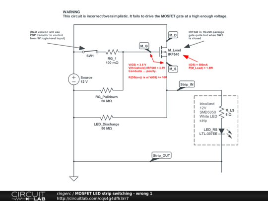
Alright folks, buckle up because today I’m gonna walk you through some real-world MOSFET madness. Seriously, I messed this up enough times that my poor breadboard practically became best friends with the trash can. Let’s get into it.

Getting Started and Hitting the Wall
So, here I was, all excited to build a simple switch for a motor using a MOSFET. I grabbed this little N-channel guy I had kicking around, wired it up quick and dirty like you do, thinking “how hard can it be?” Spoiler alert: Pretty dang hard when you’re not paying attention. I hooked up the power, gave it a signal from my little controller… and zilch. Nothing. Nada. Motor sat there staring back at me like I was an idiot. I mean, the circuit looked right? Voltage probe showed juice going in, but nada coming out the other side. Total facepalm moment.
The Lightbulb Moment (After Some Serious Google-Fu)
Frustrated, I went digging online and kept seeing this “active low” vs “active high” thing. Honestly, it sounded fancy but I was just confused. Then it clicked! My lazy setup used an N-channel MOSFET like a switch turned OFF when you hit it. Picture this: when my controller pin goes high (say, 5 volts), that little gate leg gets charged up. For an N-channel, that high gate signal is like flipping the switch ON – the motor should roar! But mine stayed stubbornly silent.
Turns out, my stupid mistake was expecting that high signal to work like flipping a light switch UP means lights ON. Totally wrong assumption. I needed the exact opposite logic for the N-channel I had. It needed that “high” signal to actually conduct and power the motor. My setup was probably trying to turn it on when the signal was low? Gah! Brain frazzle.
Later I tried a P-channel. Whooo boy, different headache. That guy is the mirror image – turning it ON requires a low signal on the gate. So if I want my controller output high to run the motor, I actually gotta connect the gate signal almost backwards. Sent my brain into knots again.
The Messy Fix (and More Mistakes)
Okay, lesson semi-learned. I rewired my circuit for the N-channel to be “active high.” This time, high signal = motor ON. Fired it up… and actually got movement! Success! But wait – why was the MOSFET getting hot enough to fry an egg after just a few seconds? Cue more frustration. Turns out I got lazy with the gate resistor, basically slapping wires together like spaghetti. Without that resistor managing the current spike charging the gate, it was like shorting the driver briefly every single time. No wonder it was cooking.

- Added a resistor between the controller and the gate leg – felt basic, but made a huge temp difference.
- Actually thought about the logic level – is my controller’s ‘high’ voltage enough to fully turn this MOSFET on? Found out some barely scraped by.
- Double-checked source/drain connections – especially crucial for the P-channel to prevent magic smoke shows.
Wrapping Up the Chaos
After all that wrestling, burned fingers, and questioning my life choices near the electronics bench, here’s the takeaway that finally stuck:
- N-channel (common): Usually, think ON when gate sees a HIGH signal (relative to its source leg). Motor connects between Drain and Power.
- P-channel: Usually flips it! Often needs ON when gate sees a LOW signal (relative to its source leg). Motor often connects between Source and Ground.
This isn’t some abstract theory – it’s the practical difference between your project working or becoming a frustrating paperweight. Don’t be like me. Know your active state for the specific MOSFET type you grab. Please. Save your sanity and maybe save a MOSFET or two from an early grave.

