Alright, so I was wrestling with this project the other day. Trying to get a small motor to behave, you know? Using one of those MOSFET thingies to control the speed. Seemed simple enough, but man, it was giving me a headache. Sometimes it’d work, sometimes it’d just do its own thing, and the motor speed wouldn’t change like I expected when I fiddled with the voltages.
I spent a good while just poking at it, swapping wires, checking connections. Classic stuff. I almost blamed the MOSFET itself, thought maybe I’d fried a couple. But then I started noticing a pattern. It wasn’t just random; it depended on how much juice I was giving it, and where.
My Little MOSFET Adventure
So, I decided to really sit down and figure out what makes these components tick. Turns out, these MOSFETs are a bit like moody teenagers. They have different zones or ways they act, depending on the voltages you throw at their terminals – the gate, the drain, and the source.
I kinda stumbled through understanding them, but here’s the gist of what I found out through trial and error, and a bit of reading between the lines of datasheets:
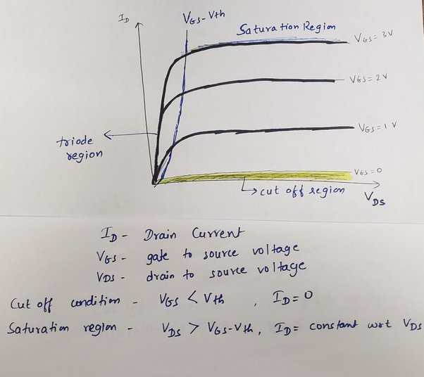
- The ‘Completely Off’ Zone: This one’s easy. If you don’t give the gate enough voltage to get its attention, the MOSFET just sits there. It’s like an open switch. No current flows from drain to source. My motor wasn’t spinning at all here, obviously.
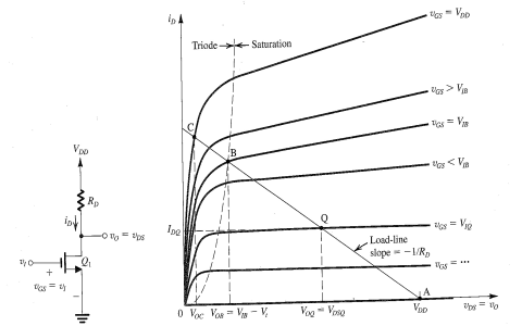
- The ‘Kinda Listening’ Zone (Ohmic/Linear): If you give the gate a decent signal, and the voltage difference between the drain and source isn’t too crazy high, the MOSFET starts to conduct. In this zone, the current flowing through it sort of follows the drain-to-source voltage. You increase that voltage, the current goes up. It acts a bit like a resistor you can control with the gate. This was where I thought all the magic should happen for controlling my motor smoothly.
But then there was the real head-scratcher, the part that was messing with my motor control.
Hitting That Saturation Wall
This is where things got weird. I’d have the gate voltage set to what I thought was a good level. Then I’d increase the voltage across the drain and source, expecting the current (and thus my motor speed) to keep climbing. But nope! After a certain point, the current just… plateaued. It hit a ceiling and wouldn’t go much higher, even if I cranked the drain-to-source voltage more.

I was like, “What gives?” I’m pushing more voltage, why isn’t more current flowing? It felt like the MOSFET just decided, “That’s enough current for this gate signal, I don’t care what you do with the drain voltage anymore.”
That, my friends, was me discovering the saturation region. In this state, the drain current becomes pretty much independent of the drain-to-source voltage. It’s almost entirely controlled by the gate voltage. So, if I wanted more current, I had to tickle the gate more, not just keep pumping voltage into the drain.
It’s like the channel inside the MOSFET that carries the current gets “pinched off” near the drain end when you’re in saturation. And how much current squeezes through that pinch point is decided by the gate.
Turns out, this isn’t a bug; it’s a feature! This saturation behavior is super important for things like amplifiers, where you want the MOSFET to act like a steady current source that’s controlled by an input voltage (at the gate), without being too affected by changes in the output voltage (at the drain). For my little motor speed controller, it meant I had to be careful. If I pushed it into saturation without realizing, trying to get more speed by just upping the main voltage supply wouldn’t work as expected. I had to manage the gate signal properly relative to the drain voltage.
So yeah, that was my little journey into the world of MOSFET saturation. Started off with a bit of “why the heck isn’t this working?” and ended with a solid “aha!” moment. It’s always satisfying when you finally get to the bottom of why your circuit is misbehaving. Now, back to that motor controller, hopefully with a bit more wisdom this time!
