Okay, here’s my take on a blog post about using a P-channel MOSFET as a switch, based on my own hands-on experience.

Alright folks, so today I’m gonna walk you through something I messed around with recently: using a P-channel MOSFET as a switch. It sounds kinda techy, but trust me, it’s not rocket science. I’ll break it down like I’m explaining it to my grandma.
The Idea
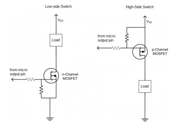
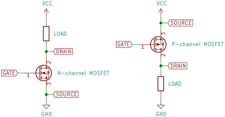
Basically, I wanted to control a small load (an LED strip, actually) with a microcontroller. I figured a MOSFET would be perfect since it can switch the power on and off electronically. Now, I could’ve used an N-channel MOSFET, but I had some P-channels lying around, so I thought, “Why not?” Plus, P-channels are cool because they’re “on” by default and need to be turned “off” with a signal.
The Parts I Grabbed
- A P-channel MOSFET (IRF4905 in my case – whatever you have handy should work, as long as it handles the voltage and current)
- A resistor (10k ohms is usually safe)
- A microcontroller (I used an Arduino Nano because I had one on my desk)
- The LED strip I wanted to control
- Some jumper wires (because wires are your friends)
- A breadboard (because soldering is for later)
Wiring It All Up
This is where things get interesting (and where I made a few mistakes, haha!). Here’s how I wired it all up:
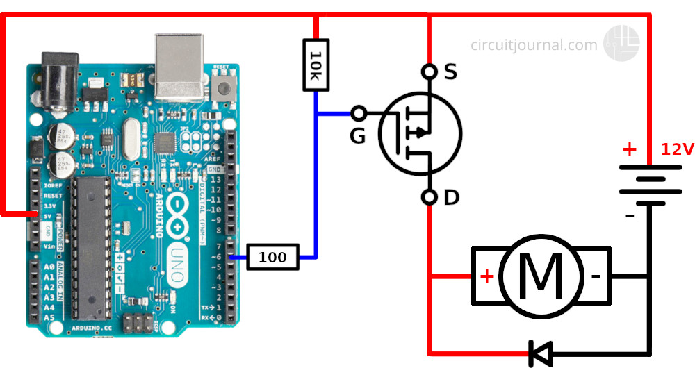
- I connected the positive (+) side of my power supply directly to the LED strip. The other end of the LED strip was connected to the Source (S) pin of the P-channel MOSFET.
- I connected the Drain (D) pin of the MOSFET to the ground (-) of my power supply.
- Here’s the important part: I connected a 10k resistor between the Gate (G) pin of the MOSFET and the positive (+) of my power supply. This keeps the MOSFET “off” by default.
- Finally, I connected a digital output pin from my Arduino Nano to the Gate (G) pin of the MOSFET. This is how I’ll control the switch.
- Make sure the grounds of your Arduino and your power supply are connected together, or things get weird.
The Code (Simple Stuff)
The Arduino code is as basic as it gets:
const int mosfetPin = 2; // the digital pin connected to the MOSFET gate

void setup() {
pinMode(mosfetPin, OUTPUT);
void loop() {
digitalWrite(mosfetPin, LOW); // Turn the MOSFET on (LED strip on)
delay(1000); // Wait for a second
digitalWrite(mosfetPin, HIGH); // Turn the MOSFET off (LED strip off)
delay(1000); // Wait for a second
Basically, setting the pin LOW pulls the Gate voltage down, turning the MOSFET on (which completes the circuit for the LED strip). Setting the pin HIGH lets the resistor pull the Gate voltage up, turning the MOSFET off.
The “Oops” Moments
Now, it didn’t all work perfectly the first time. I initially forgot the pull-up resistor, and the MOSFET was just randomly turning on and off. Adding that resistor was the key. Also, I double-checked the MOSFET pinout. Always, always double-check the pinout! Saved myself from shorting out something important.
The Result
After those minor hiccups, it worked like a charm! I could control the LED strip with my Arduino. Pretty neat, huh? It’s a simple circuit, but it’s a good building block for more complex projects.
Why This Matters
Knowing how to use a MOSFET as a switch is super useful for controlling things like motors, lights, and other higher-power devices with a microcontroller. It’s a fundamental skill in electronics, and it opens up a whole world of possibilities.
So, give it a try! You might be surprised how easy it is. And hey, if you mess something up, that’s how you learn. Happy tinkering!