Alright, so I found myself needing a specific voltage for a little project I was tinkering with. You know how it is, you’ve got a power supply that’s close, but not quite right. I could’ve bought a pre-made module, sure, but where’s the fun in that? Plus, I had a bunch of MOSFETs lying around from an old parts haul, and I figured, why not try and build a simple voltage regulator myself?

Getting Started – The Plan (or lack thereof)
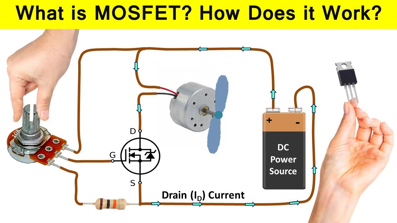
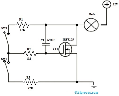
First thing, I needed a basic idea. I wasn’t aiming for something super precise, just a way to knock down a higher voltage to something more manageable and stable enough for my needs. I remembered seeing some basic MOSFET regulator circuits online ages ago. The core idea is pretty straightforward: use a Zener diode to set a reference voltage, and then a MOSFET to handle the current.
So, I grabbed a piece of paper and sketched out a rough schematic. Didn’t even use any fancy software, just pen and paper, old school style. I picked out a fairly beefy N-channel MOSFET I had, one that I knew could handle a bit of current without breaking a sweat. For the reference, I rummaged through my Zener diode collection and found one that was close to the voltage I wanted to eventually see at the output, after accounting for the gate-source voltage of the MOSFET.
Putting it on the Breadboard
Next, it was time for the breadboard. I always start on a breadboard. Always. Saves so much pain later if you mess something up. I stuck the MOSFET in, then the Zener, a couple of resistors here and there – one to limit current to the Zener, and another as a pull-down for the gate, just in case.
I hooked up my bench power supply as the input. Started with a low voltage, of course. You don’t just slam 24 volts into a new circuit unless you like smoke. I slowly cranked it up. My multimeter was hooked to the output, watching nervously.
First attempt? Well, it sort of worked. The voltage was in the ballpark, but it wasn’t super stable when I tried to draw a bit of current. It sagged more than I liked. Classic. I realized my initial resistor values were probably a bit off, maybe starving the Zener or not driving the MOSFET gate hard enough.

Tweaking and Testing – The Fun Part
This is where the real “engineering” happens, if you can call it that. It’s mostly trial and error. I swapped out the resistor feeding the Zener for a smaller value to give it a bit more juice. That helped. Then I played with the gate resistor a bit.
I used a few power resistors as a dummy load. Started with a light load, then gradually increased it. The MOSFET started to get warm. Not surprising, it’s a linear regulator after all, so it’s basically burning off the extra voltage as heat. I made a mental note that if I was going to use this for anything serious, a heatsink would be non-negotiable.
Here’s what I was looking for:
- Output Voltage Stability: How much did it drop under load?
- Heat: Was the MOSFET going to turn into a tiny volcano?
- Response: Did it react okay if I quickly changed the load? (Spoiler: these simple ones aren’t super fast, but good enough for many things).
After a bit of fiddling, I got it to a point where the output voltage was reasonably stable for the current I needed. It dropped a little under full load, maybe a few tenths of a volt, which was acceptable for my application. The MOSFET was definitely getting toasty, though. I touched it – carefully – and yeah, it was hot. A proper heatsink would be essential for continuous operation at higher currents.
Was it Worth It?
So, did it work? Yes, eventually. It did what I needed it to do. It wasn’t the most efficient thing in the world, and definitely not a precision regulator, but for a quick and dirty solution using parts I already had, I’d call it a success. The main thing is, I got my hands dirty, played around with some components, and got a working circuit out of it.

What I learned (or re-learned):
- Simple circuits can still be finicky.
- Heatsinking is super important for linear regulators, especially with MOSFETs handling any decent amount of power.
- Breadboarding first is always the way to go. Imagine soldering all that up just to find out a resistor value was way off.
- It’s satisfying to build something yourself, even if it’s simple.
Would I use this exact design for a critical application? Probably not without a lot more refinement. But for a hobby project, or when you just need to drop a voltage quickly and don’t have the right part on hand, it’s a neat little circuit to know. And it was a good way to spend an afternoon. Now, to find a suitable heatsink for that MOSFET before I actually put this into service…

