Alright, let’s talk about MOSFET schematics. Not the super complicated textbook stuff, but my own journey wrestling with them. You know, trying to actually get something to work.
It all kicked off because I had this little project. I needed to control something that drew a bit more current than my little microcontroller pin could handle. A bunch of LEDs, I think it was. Someone mentioned “MOSFET,” and down the rabbit hole I went.
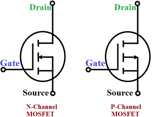
First thing I did was look up “MOSFET schematic.” Seemed simple enough, right? Three little legs on the symbol. Looked like a weird kind of tap. Gate, Drain, Source. Okay, names. But what did they do?
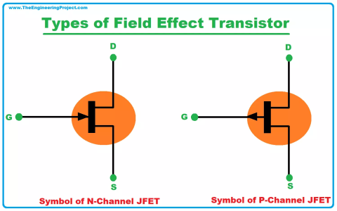
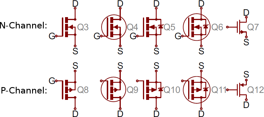
I remember staring at those diagrams. N-channel, P-channel… which one did I need? And why were some symbols drawn one way, and others slightly different? It felt like everyone had their own secret handshake for drawing these things. I just wanted to turn my lights on and off, man.
So, I decided to just dive in and try to sketch one out. I picked an N-channel one, because that seemed to be what most folks used for switching things to ground. I got out my notebook – yeah, I still use paper sometimes, helps me think – and started drawing. Microcontroller pin to the Gate. LEDs and a resistor on the Drain side, going to my positive supply. Source to ground. Seemed logical.
My first try? Nothing. The LEDs just stared back at me, unimpressed. I probably had it wired wrong on my breadboard, to be honest. It’s one thing to draw it, another to actually poke wires into tiny holes.
Then I read somewhere you might need a resistor on the gate. Why didn’t the first diagram I saw mention that? Or maybe I just missed it. So, I added a small resistor, like 10k, between the microcontroller and the gate. Still a bit iffy.
And then there was the pull-down resistor. Someone on a forum swore by them for N-channel MOSFETs, to keep the gate from floating when the microcontroller pin wasn’t actively driving it high or low. So, I added another resistor, this one from the gate to ground. My schematic was starting to look less like the ‘simple’ examples and more like a bit of a cat’s cradle.
I must have redrawn that little section of my schematic half a dozen times. Each time I changed something on the breadboard, I’d update my drawing. It was slow. Sometimes frustrating. I definitely let out the magic smoke from one or two of those little black chips. They don’t like being wired backward, turns out. Who knew?
But then, finally, it worked. The LEDs blazed to life when my microcontroller said so. It was a small victory, but it felt good. That little hand-drawn schematic, with its crossed-out lines and scribbled notes, was my Rosetta Stone for that MOSFET.
What I figured out, through all that fiddling, wasn’t just how to draw the schematic. It was more about what each part did. The gate resistor wasn’t just a random component; it was there to protect the microcontroller. The pull-down resistor made sure the MOSFET turned off properly and didn’t just hover in some weird half-on state.

So yeah, drawing a MOSFET schematic seems easy. And the basic symbol is. But getting it to a point where it actually, reliably works in your circuit? That’s where the practice comes in. It’s not just connecting lines. It’s understanding the ‘why’ behind those lines and components.
Now, when I see a MOSFET in a schematic, it doesn’t look so cryptic. I still have to check the part number and whether it’s N or P, but the basic idea of how it’s being used to switch something? That finally clicks, thanks to that one frustrating, then finally rewarding, little LED project.