Alright, let’s talk about these MOSFET things. When I first bumped into them, I was just trying to get a bigger light to turn on with my little microcontroller. Seemed simple, right? Wrong. Those datasheets, man, they looked like some secret code.

People online kept saying, “Oh, it’s just an electronic switch!” Easy for them to say. My first few attempts involved more smoke than light. I swear, I thought I was cursed. I was probably just connecting things all over the place, hoping for the best. Not a great strategy, by the way.
Getting My Hands Dirty
So, I got a handful of those N-channel MOSFETs, I think they were the IRFZ44N type, super common. Decided I was just gonna poke at it until something happened. I grabbed an LED strip I had lying around, a 12V power brick, and my trusty breadboard.
My first few tries? Total bust. Either nothing happened, or the LED strip was so dim you’d think it was shy. I was definitely mixing up the Gate, Drain, and Source pins. I’m pretty sure I connected the Gate directly to the 12V supply at one point. Let’s just say the MOSFET didn’t appreciate that.
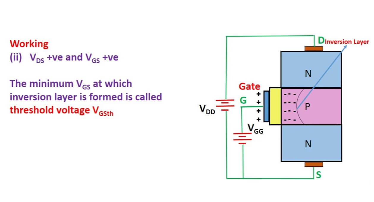
The big “aha!” moment for me was understanding that the Gate is like the magic key. You tickle it with a tiny bit of voltage, and BAM, the main power can flow through the other two legs. It’s not about forcing power through the gate; it’s about the gate allowing power to flow between the Drain and Source.
My Basic N-Channel Setup that Finally Worked
Here’s what I eventually figured out for an N-channel MOSFET, to control that LED strip:

- The Load (my LED strip): Connected one end to the positive (+) of my 12V power supply. The other end of the LED strip went to the Drain pin of the MOSFET.
- The MOSFET’s Source pin: This guy went straight to the ground (-) of my 12V power supply.
- The MOSFET’s Gate pin: This was the control. I connected this to a digital output pin on my Arduino.
- Crucial bit: I also added a resistor, something like 10k Ohms, between the Gate pin and Ground. This is a “pull-down” resistor. Without it, the gate can kind of float around and the MOSFET might turn on or off when you don’t want it to. I learned this when my project started acting possessed, flickering like crazy.
So, when my Arduino pin sent out 5V (HIGH), the MOSFET turned ON, and my LED strip lit up bright! When the Arduino pin went to 0V (LOW), the MOSFET turned OFF. Simple as that, once I stopped trying to reinvent the wheel and actually followed a proper diagram.
Then Came P-Channels…
Just when I thought I had it figured out, I stumbled upon P-channel MOSFETs. They do the same job, but kinda backwards. You usually use them for “high-side switching,” meaning you put the MOSFET between the positive power supply and your load. And to turn them ON, you typically pull their Gate LOW, towards ground. My brain hurt for a bit trying to get that straight. For N-channels, you typically switch on the low side (between the load and ground) and apply a positive voltage to the gate (relative to the source) to turn it on.
I remember this one project, I was building an automatic watering system for my sad little herb garden on the balcony. The tiny water pump needed more power than my microcontroller could safely provide directly. I was stumped for a bit, thinking I’d need complicated relay circuits. Then I remembered these MOSFETs. Popped an N-channel one in there to switch the pump on and off based on a soil moisture sensor. Worked like a charm! My basil plant, which was on its last legs, actually perked up. Felt like a proper electronics wizard for a day. It’s funny how these little components, once you get the hang of them, open up so many possibilities.

