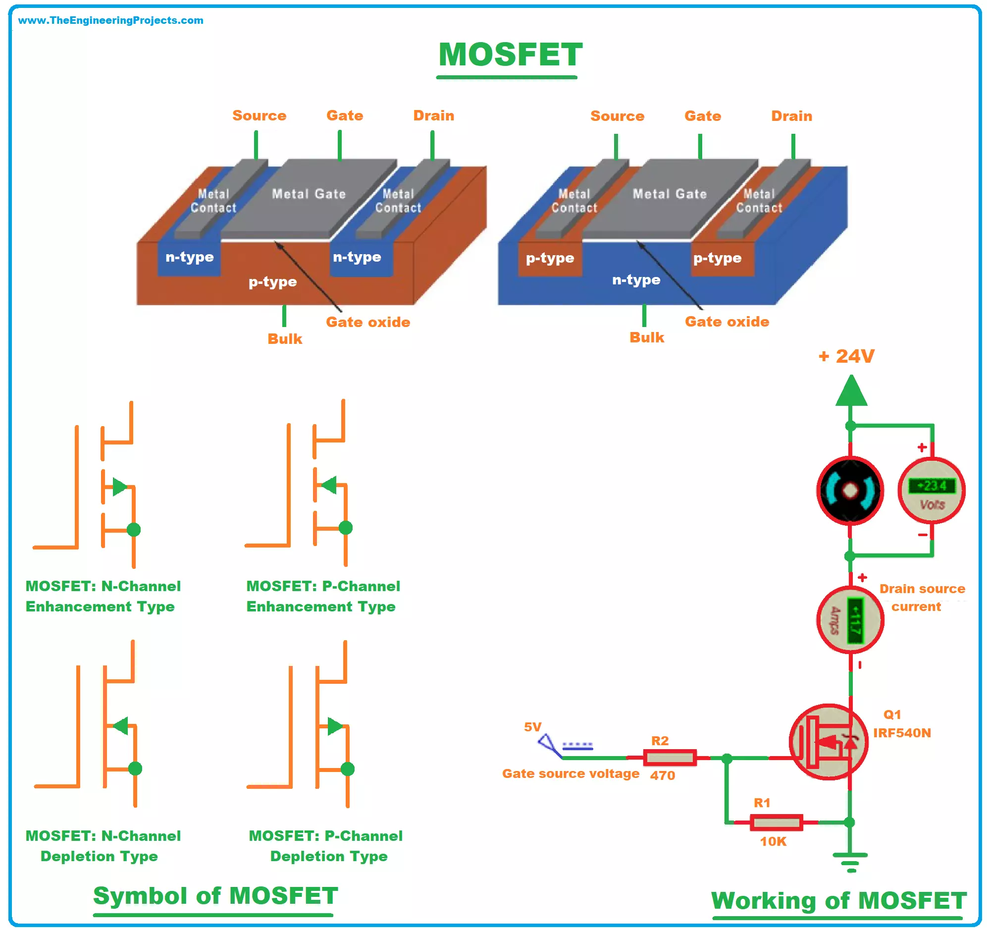
Alright, so I’ve been messing around with MOSFETs again, specifically trying to really get a feel for their operating regions. It’s one of those things you read about, but until you actually sit down and poke at it, it doesn’t quite click, you know? So, I thought I’d share what I did and what I saw.

My Little Experiment Setup
Nothing fancy, really. I grabbed a common N-channel MOSFET, a breadboard, a couple of variable power supplies – one for the gate-source voltage (Vgs) and one for the drain-source voltage (Vds) – and a couple of multimeters to measure currents and voltages. I wanted to see this stuff happen with my own eyes, not just on a simulator.
Starting from Zero: The Cut-Off Region
First thing I did was set the gate-source voltage (Vgs) to zero, or even a little negative just to be sure. I then started to slowly crank up the drain-source voltage (Vds). And guess what? Pretty much nothing happened. The multimeter measuring the drain current (Id) just sat there, reading close to zero. It was like the MOSFET was an open switch. That’s the cut-off region for you. No gate voltage, no party. The channel between drain and source just isn’t there, so no current can flow, no matter how much Vds you apply (within reason, don’t wanna fry the thing!).
- Applied Vgs = 0V.
- Varied Vds from 0V up to a few volts.
- Observed Id was practically zero.
Pretty straightforward, but it’s the foundation. The MOSFET is OFF.
Getting Things Moving: The Triode (or Linear) Region
Next, I started to give the gate some positive voltage. I set Vgs to something above the threshold voltage – say, a couple of volts. Then, I kept Vds relatively low and started to increase it slowly from zero. Now we’re talking! Current started to flow from drain to source. What I found interesting was that as I increased Vds (while Vgs was fixed and Vds was still less than Vgs minus the threshold voltage), the drain current Id went up kinda linearly with Vds. The MOSFET was acting like a resistor. And if I increased Vgs a bit more, this “resistance” would decrease, meaning more current for the same Vds. This is the triode region, or some folks call it the linear region. It’s like a tap you can control.
- Set Vgs to a value above the threshold voltage (e.g., 2V or 3V).
- Slowly increased Vds from 0V.
- Observed Id increasing as Vds increased.
- Noticed that if I upped Vgs, Id would be higher for the same Vds.
So, in this state, it’s like a voltage-controlled resistor. Handy for some analog stuff, I guess.

Hitting the Limit: The Saturation Region
This is where it got really distinct for me. I kept Vgs fixed at a decent level (say, 3V). Then I started to increase Vds further. Initially, Id increased with Vds, just like in the triode region. But once Vds got high enough (specifically, when Vds became greater than Vgs minus the threshold voltage), something changed. Increasing Vds further didn’t really make Id increase much anymore! The current kinda leveled off, or “saturated.” It was now acting more like a constant current source, with the value of that current being controlled by Vgs. If I wanted more current, I had to increase Vgs. If I lowered Vgs (but kept it above the threshold), the saturated current level would be lower.
- Kept Vgs fixed at a value well above threshold.
- Increased Vds past the point where Vds > (Vgs – Vth).
- Observed that Id stayed pretty much constant, even if I increased Vds more.
- Changing Vgs would change this constant current level.
This saturation region is super important for amplifiers, and also when you use a MOSFET as a switch – you want to drive it hard into saturation to get the lowest possible resistance when it’s “ON” (though that’s a bit of a mix with deep triode, the goal is minimal voltage drop).
Why Bother With All This?
Well, knowing these regions isn’t just for exams. When I’m designing a circuit, whether it’s a simple switch for an LED or something more complex, understanding how the MOSFET will behave based on the voltages I give it is crucial. If I want it to be a good switch, I need to make sure I’m either slamming it into cut-off (fully OFF) or deep into the triode/ohmic region (fully ON with low resistance). If I’m building an amplifier, I’m probably aiming for the saturation region to get that controlled current behavior.
It took a bit of hands-on fiddling, watching those multimeter readings change, to really internalize it. Textbooks are great, but seeing it happen makes a world of difference. So yeah, that was my little journey through the MOSFET operating regions today. Hopefully, my scribbles help someone else get a practical feel for it too!

