Alright, so today I figured I’d walk you through a little adventure I had: getting a MOSFET H-bridge up and running. I’ve been meaning to get a DC motor spinning both forwards and backwards for a project, and this seemed like the way to go. It’s one of those things that looks simple on paper, but let me tell you, the devil is in the details, as they say.
Getting Started – The Idea
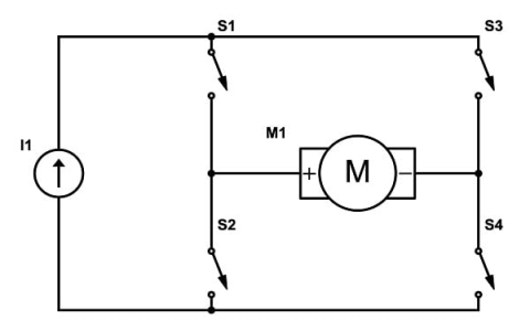
So, the plan was straightforward. I needed to control a decently sized DC motor, and I wanted to be able to reverse its direction and control its speed. Relays are too clunky and noisy for my taste, and I wanted something a bit more elegant. That’s where the H-bridge comes in. And using MOSFETs? Well, they’re efficient, fast, and can handle a good amount of current, so it felt like the right path.
I’d seen a bunch of diagrams online. Some looked super complicated with tons of parts, others looked almost too simple. You know how it is, you try to find that sweet spot.
Gathering the Bits and Pieces
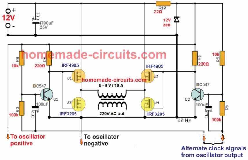
First things first, I needed the MOSFETs. I opted for N-channel MOSFETs for all four positions initially. I’d read they generally have better performance, lower Rds(on) and all that. But then the reality of driving high-side N-channel MOSFETs hit me. You need a voltage higher than your main supply to turn them on properly. Ugh. This is where things started to get a bit more involved than just slapping four transistors together.
So, my options were:
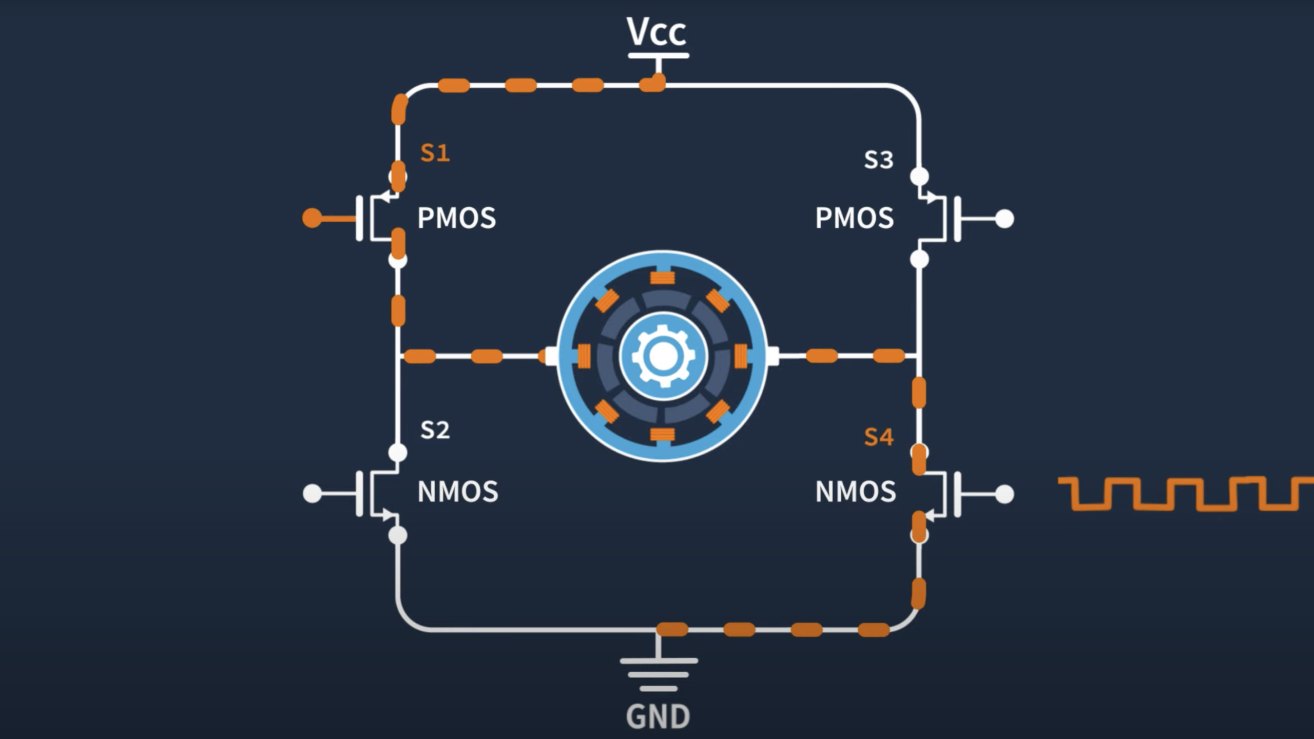
- Use P-channel MOSFETs for the high side and N-channel for the low side. This simplifies driving a bit, but P-channels often aren’t as good performance-wise.
- Stick with all N-channels and figure out a gate driver solution. This could be a dedicated H-bridge driver IC, or building a discrete bootstrap circuit.
I actually tried the P-channel/N-channel mix first on a breadboard. It kinda worked, but driving the P-channels directly from a microcontroller logic level wasn’t ideal if the motor voltage was higher. The gate-source voltage (Vgs) limits, you know. Got to be careful not to pop them.
The Build Process – And a Few Hiccups
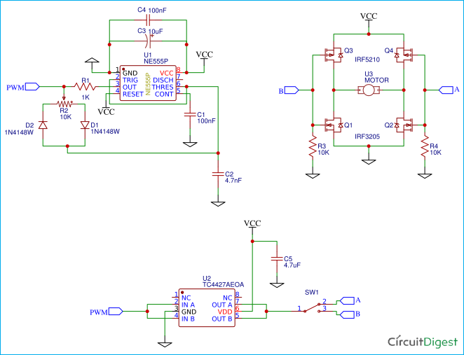
I eventually decided to go with a dedicated H-bridge driver IC for a more robust solution with all N-channel MOSFETs. These chips are pretty neat; they handle the level shifting and often have built-in protection features like shoot-through prevention (where both MOSFETs on one side of the bridge accidentally turn on at the same time – bad news!).
My first attempt at soldering everything onto a perfboard was… well, let’s just say it wasn’t my prettiest work. Lots of wires, and I was double and triple-checking every connection. It’s easy to make a mistake that lets out the magic smoke.
And speaking of magic smoke, yeah, I had a moment. During one of my earlier tests, before I fully committed to the driver IC and was still messing around with discrete components, I managed to create a short. One of the MOSFETs got incredibly hot, incredibly fast. Lesson learned: always current-limit your power supply during initial tests! A small resistor in series, or a bench supply with adjustable current limiting, can be a lifesaver for your components.
I also had to be really careful about the gate drive signals. The rise and fall times matter, especially if you’re trying to switch quickly for PWM speed control. Weak gate drive means the MOSFET spends too much time in its linear region, acting like a resistor, and that means heat. Lots of heat.
Getting it to Work – The “Aha!” Moments
Once I got the H-bridge driver IC properly wired up to the four N-channel MOSFETs, things started to look up. The driver IC took care of generating the correct gate voltages for the high-side MOSFETs, which was a huge relief.
Connecting the motor was the next step. I started with a small, low-power motor just to be safe. I wrote some simple code for my microcontroller (an Arduino, in this case, just for quick testing) to send signals to the H-bridge driver: one signal for direction, another for PWM speed control.
And then, the moment of truth. I uploaded the code, powered everything on (with bated breath, of course), and sent the command to go forward. The motor spun! Then I sent the command to reverse. It spun the other way! Success! It’s always such a good feeling when something you’ve been wrestling with finally clicks into place.
I also made sure to implement some dead-time in my microcontroller logic before I fully relied on the driver IC’s protection. Dead-time is just a small delay between turning one MOSFET off and turning the other one on in the same leg of the H-bridge. It’s an extra layer of protection against shoot-through.
Final Thoughts and What I Learned
Building this H-bridge was definitely a learning experience. It’s not just about connecting a few components; it’s about understanding how they interact, especially with gate driving and potential pitfalls like shoot-through.
A few key takeaways for me were:

- Gate driving is critical: Especially for high-side N-channel MOSFETs. Don’t skimp on this. Driver ICs are your friends.
- Heat is the enemy: If you’re pushing decent current, expect your MOSFETs to get warm. Heat sinks might be necessary. And proper gate drive helps minimize switching losses.
- Test carefully: Start with low power, current limit your supply if you can, and double-check your wiring. Magic smoke is not a feature.
- Dead-time is important: Even if your driver IC claims to have shoot-through protection, a little software dead-time doesn’t hurt.
It took a bit of time, a few frustrating moments, and one slightly singed MOSFET, but I got there. Now I have a reliable way to control my DC motors. It felt good to go through the process from theory to a working circuit. On to the next part of the project!