Okay, let’s talk about getting my head around MOSFET circuit symbols. It wasn’t something I picked up instantly, took a bit of staring and scribbling.
So, I needed to figure out these symbols for a little project I was messing with. Opened up a schematic, saw these weird little drawings, and knew I had to understand what was what. First thing, you got three connections sticking out: Drain, Gate, and Source. Usually labeled D, G, S. Easy enough, right?
But then, there were different versions of the symbol. That tripped me up for a bit. I started digging around, looking at datasheets and basic electronic guides. The main thing I needed to sort out was N-channel versus P-channel.
Figuring out N-Channel and P-Channel
This turned out to be about the arrow. There’s always an arrow on the Source leg, or connected to it somehow. Here’s the trick I finally nailed down:
- Arrow pointing IN (towards the channel/middle part): That’s an N-channel MOSFET.
- Arrow pointing OUT (away from the channel/middle part): That’s a P-channel MOSFET.
Once I got that straight, things started making more sense. I just had to remember ‘N’ means arrow points ‘iN’. Kind of silly, but it worked for me.
Enhancement vs. Depletion Mode
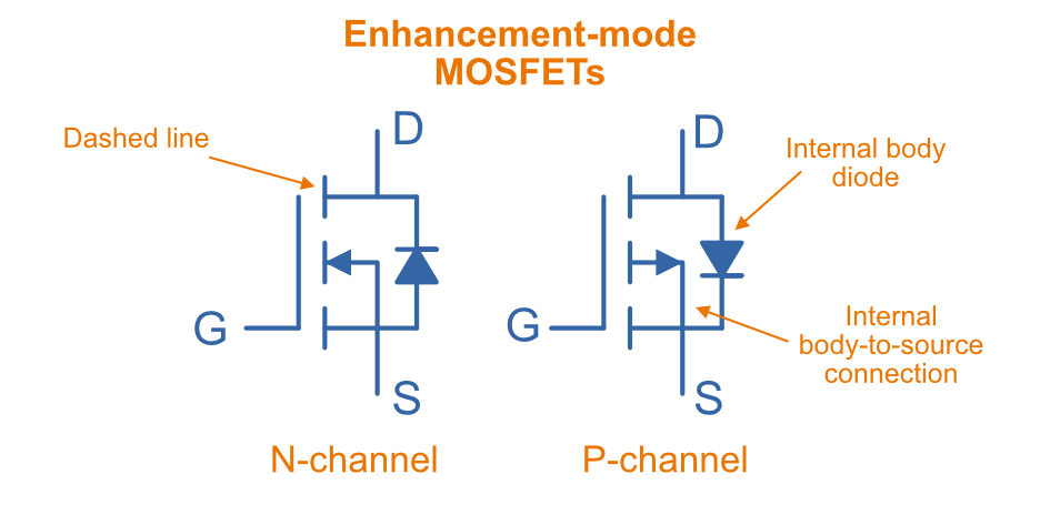
The next puzzle was the line connecting the Drain and Source inside the symbol. Sometimes it was solid, sometimes it was broken into segments.
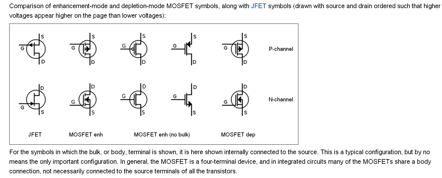
- Broken line: This is an Enhancement mode MOSFET. These are the most common ones I run into. Basically, it’s normally OFF. You need to apply voltage to the Gate to turn it ON, to enhance the channel so current can flow.
- Solid line: This means Depletion mode. These are normally ON. You need to apply voltage to the Gate to turn it OFF, to deplete the channel. Don’t see these as often in my hobby stuff.
So, most times I’m looking at a symbol with a broken line and an arrow pointing in (N-channel Enhancement) or a broken line and an arrow pointing out (P-channel Enhancement).
Putting it Together
I spent some time just drawing these out. Like, literally sketching the N-channel enhancement symbol, labeling D, G, S, making sure the arrow pointed in and the channel line was broken. Did the same for the P-channel enhancement. Repetition helped lock it in.
Sometimes you also see a diode drawn inside the symbol, connecting the Source and Drain. That just represents the body diode that’s naturally part of the MOSFET structure. Its direction depends on whether it’s N-channel or P-channel, usually pointing from Source to Drain for N-channel and Drain to Source for P-channel (if you think about conventional current flow).
After messing around with drawing them and looking at simple circuits like using a MOSFET as a switch, it started to click. It’s really just about recognizing those key features: the arrow direction and the channel line type. Took a bit of practice, but now when I see a schematic, I can spot the MOSFET type pretty quickly. It’s not magic, just learning the language of the symbols.