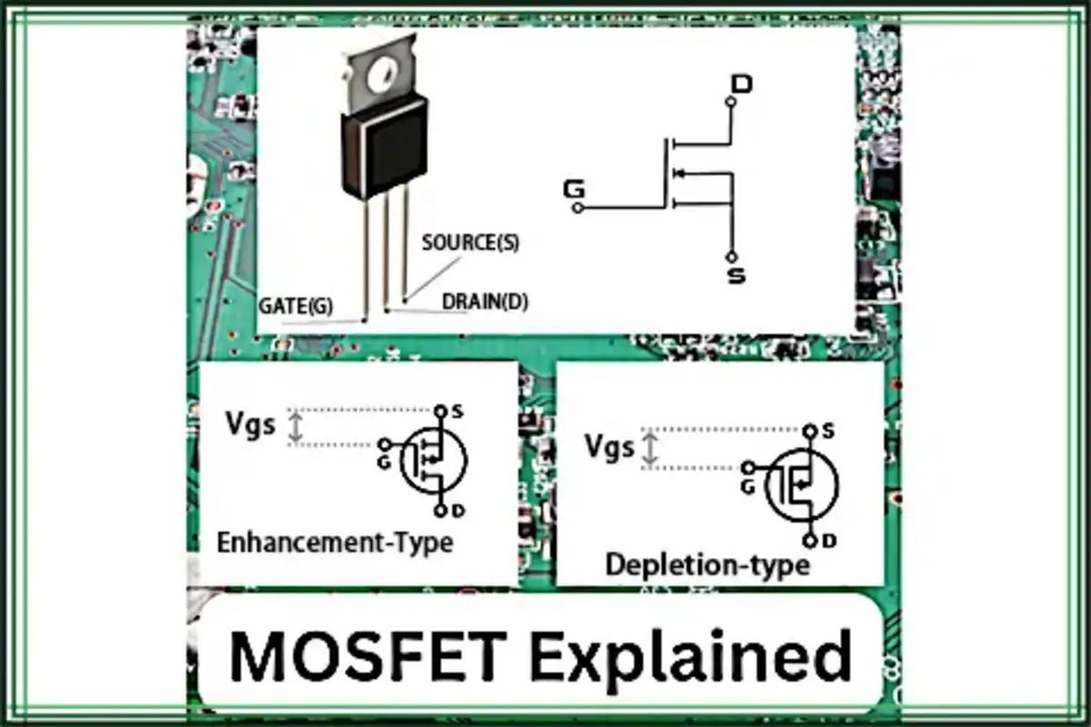
Okay, let’s talk about putting together a basic MOSFET circuit. I needed to switch a small 12V motor for a little project I was messing with, something my Arduino couldn’t handle directly, obviously. So, time to break out the MOSFETs.
Getting Started
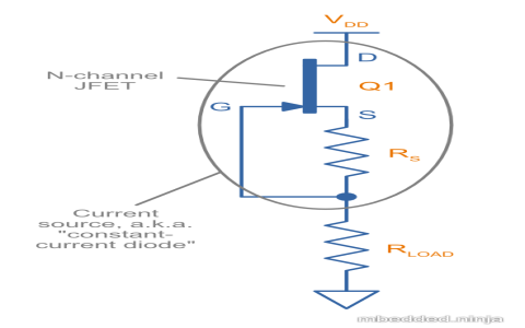
First thing, I had to figure out the circuit. Didn’t need anything complex, just a simple on/off switch controlled by a digital pin. I remembered the basic setup for an N-channel MOSFET used as a low-side switch. Found a diagram online just to refresh my memory – it’s easy to forget the details if you haven’t done it in a while.
The plan was straightforward: use the Arduino’s output pin to control the MOSFET’s gate, and the MOSFET would switch the ground connection for the motor.
Gathering the Bits and Pieces
I went digging through my component drawers. Found my trusty stash of IRFZ44N MOSFETs. They’re oldies but goodies, cheap and handle a decent amount of current. Grabbed a few just in case I blew one up – happens sometimes, right?
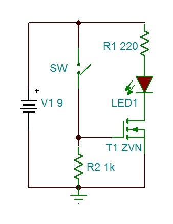
Needed resistors too. A 10k Ohm resistor seemed about right for a pull-down on the gate. You need this to make sure the gate doesn’t float when the Arduino pin isn’t actively driving it HIGH. Learned that lesson the hard way on a previous project where things were acting weirdly.
Also needed:

- My Arduino Uno
- A breadboard
- Jumper wires (lots of them, they always disappear)
- The small 12V DC motor I wanted to control
- A 12V power supply
- A flyback diode (like a 1N4007) because motors kick back voltage when they turn off, and I didn’t want to fry my MOSFET or the Arduino.
Putting It All Together
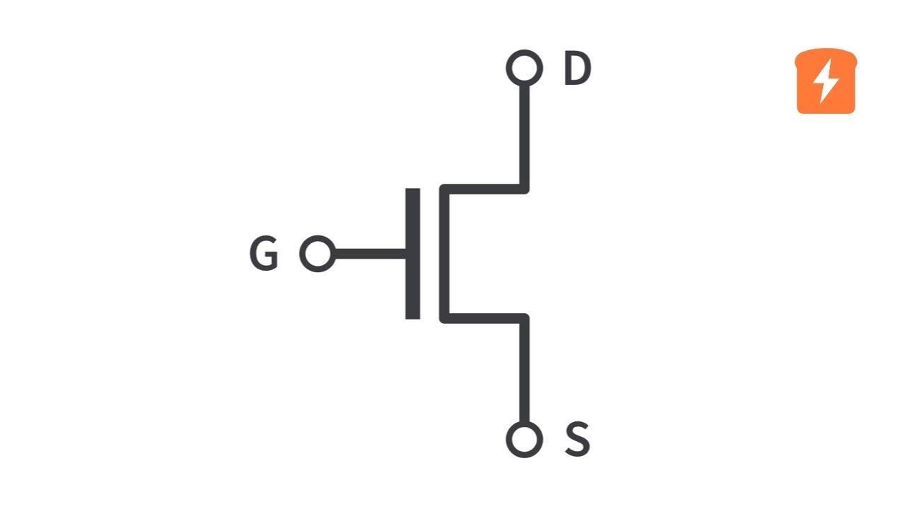
Okay, onto the breadboard. I stuck the IRFZ44N in, legs spread comfortably. Had to quickly look up the pinout again – Gate, Drain, Source (GDS). It’s usually printed on the component, but my eyes aren’t what they used to be!
Source pin: Connected this straight to the ground rail of the breadboard. Easy.
Drain pin: Connected one lead of the motor to this pin.
Motor’s other lead: Connected this to the positive (+) terminal of my 12V power supply.
Gate pin: Connected this to digital pin 9 on my Arduino. Also, connected the 10k resistor between this Gate pin and the ground rail. This is the pull-down resistor.
Ground connection: This is critical! I connected the ground rail of the breadboard (where the MOSFET Source and the pull-down resistor were connected) to the ground (-) terminal of the 12V power supply AND to one of the GND pins on the Arduino. Everything needs a common ground reference, or it just won’t work right. Forgot this once and spent an hour scratching my head.
Flyback Diode: Connected the 1N4007 diode across the motor terminals. The striped end (cathode) went to the 12V positive side, and the other end (anode) went to the MOSFET’s Drain pin. This gives the inductive kickback current a safe path to circulate instead of zapping my circuit.
Coding and Testing
Wrote a super simple sketch for the Arduino. Just the basic blink example, modified to turn pin 9 on and off.
Something like:
void setup() { pinMode(9, OUTPUT); }
void loop() { digitalWrite(9, HIGH); delay(2000); digitalWrite(9, LOW); delay(2000); }
Uploaded the code. Connected the 12V power supply. Plugged in the Arduino via USB.
Held my breath for a second… and it worked! The motor spun up when pin 9 went HIGH and stopped when it went LOW. Felt the MOSFET after a minute – barely warm, which was good. The IRFZ44N was more than capable for this little motor.
Final Thoughts
So yeah, that was my little adventure getting a MOSFET switch working again. It’s a fundamental circuit, really useful for controlling bigger loads with microcontrollers. The key things I always try to remember are the pull-down resistor on the gate and the flyback diode for inductive loads like motors or solenoids. Oh, and making absolutely sure all the grounds are connected together! Simple stuff, but easy to forget, and it causes headaches if you do. Glad it went smoothly this time around.