Okay, so I decided to mess around with making a simple inverter using MOSFETs the other day. Had some parts lying around and thought, why not give it a shot?

Getting Started
First thing, I rummaged through my component bins. Found a couple of N-channel MOSFETs, I think they were IRFZ44Ns or something similar, pretty common ones. Needed a transformer too, so I salvaged a small center-tapped one from an old power supply, maybe 12V input kind of thing. Grabbed a breadboard, some jumper wires, a few resistors (like 100 ohm and 10k ohm), and my trusty 12V lead-acid battery.
Sketching Out the Idea
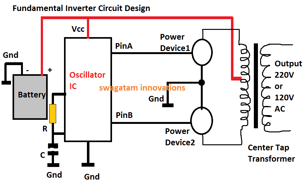
Didn’t go for anything too fancy. I just wanted to see if I could get AC out from DC. The basic idea was to make the MOSFETs switch on and off, one after the other. This switching action would push current back and forth through the two halves of the transformer’s primary winding. This changing magnetic field should then create AC voltage on the secondary side. Simple push-pull setup.
To make the MOSFETs switch, I needed some kind of oscillator. I could have used a 555 timer chip, but I decided to try an even simpler approach first using just a couple of transistors and resistors to make a basic multivibrator circuit. Just something to generate alternating pulses to feed the MOSFET gates.
Putting it Together
So, I stuck the two MOSFETs onto the breadboard. Connected the center tap of the transformer’s primary winding to the positive terminal of my 12V battery. Then, I connected the drain of each MOSFET to one end of the primary winding. The source pins of both MOSFETs went straight to the negative terminal (ground) of the battery.
Next up was the driving circuit. I built that little transistor oscillator on another part of the breadboard. The outputs from this oscillator needed to go to the gates of the MOSFETs. I put a small resistor (around 100 ohms) in series with each gate, just to be safe and maybe limit the current a bit. Connected the oscillator outputs through these resistors to the respective MOSFET gates.
Double-checking connections was key here. It’s easy to mix things up on a breadboard.
Powering Up and Fixing Stuff
Alright, moment of truth. I connected the battery. At first… nothing spectacular. I checked the oscillator with my multimeter, saw some voltage switching, so that part seemed okay. But no AC output from the transformer secondary.
Then I touched the MOSFETs. Uh oh. One was getting pretty warm, almost hot. That’s usually not a good sign. Disconnected the battery quickly.
I suspected maybe the switching wasn’t clean, or maybe both MOSFETs were turning on slightly at the same time (shoot-through). Re-checked the oscillator outputs and the gate connections. Found a loose wire on one of the gate resistors. Pushed it back in firmly.
Also realized my simple transistor oscillator might not be driving the MOSFET gates hard enough or fast enough. MOSFET gates can act like small capacitors and need a decent pulse to switch quickly. But decided to try again with the connections secured.

Getting Some Results
Connected the battery again. This time, no instantly hot MOSFETs. Progress! I grabbed my multimeter, set it to AC voltage, and carefully probed the secondary winding of the transformer. Hey! Got a reading! Wasn’t a perfect mains voltage replica or anything, maybe around 50-60V AC (it was a step-up transformer). The waveform was probably awful, likely a square wave, but it was AC.
Just for kicks, I tried connecting a small, low-wattage incandescent bulb (like an old flashlight bulb) to the output. It lit up! Dimly, but it worked. That felt pretty good.
- Got DC converted to AC.
- Used basic parts I had on hand.
- Managed to troubleshoot a heating issue.
Final Thoughts
So yeah, the little MOSFET inverter kinda worked. It wasn’t efficient, the output was definitely not a clean sine wave, and the MOSFETs still got a bit warm after running for a minute, meaning losses. For anything serious, you’d need a proper driver IC, better heat sinking, maybe some filtering on the output, and a more sophisticated design like an H-bridge for better control.
But as a quick experiment to see the principle in action? Totally worth it. Just messing around with components and seeing something tangible happen is always fun. Learned a bit more about driving MOSFETs too.