Alright, so today I’m diving into MOSFETs. I’ve been messing around with these little guys for a while, and figured it’s time to actually understand how they work, instead of just blindly following tutorials.
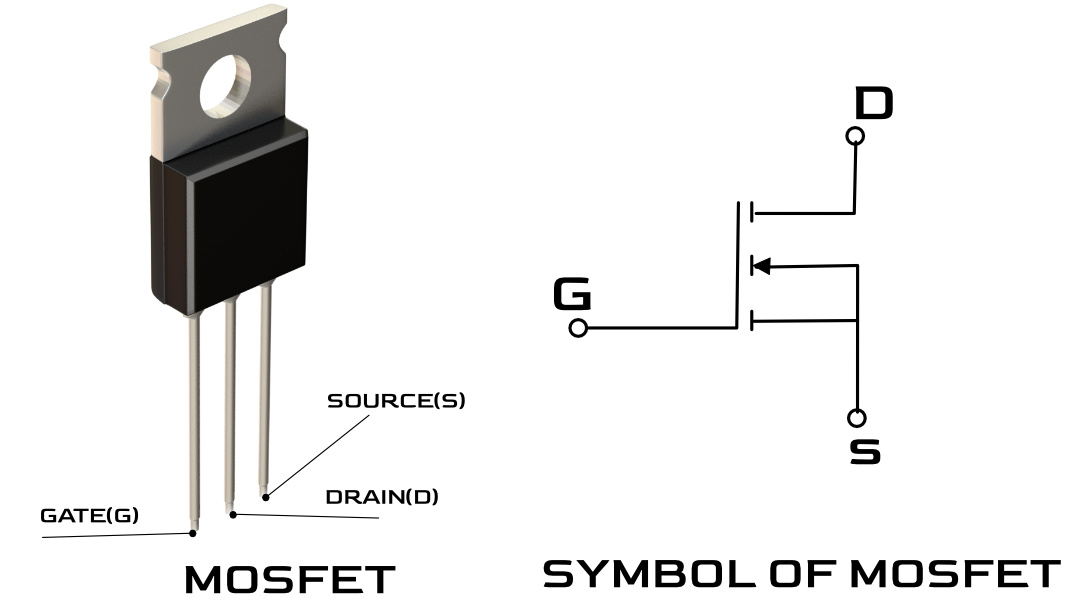
First things first, grabbing a MOSFET. I had a bunch of IRF520s lying around – salvaged from some old projects. Nothing fancy, but good enough to get started. Pulled out my breadboard, multimeter, power supply, and a handful of resistors. Gotta keep things organized… sort of.
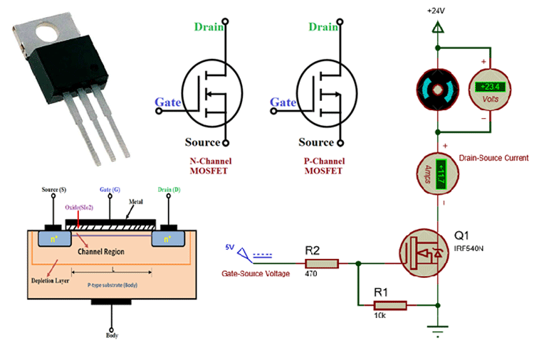
Okay, so the plan was simple. I wanted to see how the gate voltage affects the current flow between the drain and the source. I started by setting up a basic circuit. Power supply hooked up, resistor in series with the drain to limit the current, and the MOSFET sitting there waiting for its marching orders. Grounded the source, naturally.
Time for the fun part: the gate. I connected the gate to a potentiometer, which was connected to the power supply. This way, I could adjust the gate voltage from 0V up to whatever my power supply was set to (usually around 5V or 9V to avoid frying anything). Started at 0V, and measured the drain current using my multimeter. Nada. Expected, since the MOSFET is off at 0V.
Slowly cranked up the gate voltage. Watched the drain current. Still nothing. Okay, maybe these MOSFETs are dead? Swapped it out for another one. Same thing. Hmm… Re-checked my wiring. Yep, everything seems right. Then it hit me – the datasheet! Turns out, these IRF520s have a Vgs(th) (gate-source threshold voltage) of like, 2V to 4V. Meaning, I need at least 2 volts on the gate just to start seeing any current flow.
Okay, crank it up some more! Finally, at around 3V on the gate, I started to see a trickle of current. Bingo! Turned the pot even more, and the current steadily increased. Cool! I was actually controlling the current through the MOSFET with just the gate voltage. This is what it’s all about.
Played around with different resistor values. Used smaller resistors, the current went up faster with increasing gate voltage. Bigger resistors, the current increase was slower. Makes sense – Ohm’s Law, baby!
Then I got curious about switching speeds. I tried quickly switching the gate voltage on and off, expecting to see the drain current respond instantly. But it didn’t. There was a slight delay. Turns out, the gate has capacitance, and it takes a little time to charge up and discharge. This is important for high-speed switching applications.
Finally, I tried using the MOSFET as a switch. Connected an LED to the drain with a current-limiting resistor. When I applied a voltage to the gate, the LED lit up. Removed the gate voltage, and the LED went off. Boom! A solid-state switch, controlled by voltage. Pretty neat.
Lessons learned? Datasheets are your friends! Don’t assume things. Double-check your wiring. And most importantly, have fun and don’t be afraid to experiment. That’s how you really learn.
- MOSFETs are voltage-controlled current sources.
- The gate voltage controls the current flow between the drain and source.
- There’s a threshold voltage you need to overcome before the MOSFET starts conducting.
- Gate capacitance affects switching speed.
That’s it for today. Now, I’m gonna go find another electronic component to mess with. Maybe transistors next?