Okay, let’s talk about MOSFETs. Not the super deep-dive textbook stuff, but how I actually got my hands dirty with them.

My First MOSFET Adventure
So, I was messing around with a little project, trying to control something that needed more juice than my little microcontroller pin could handle directly. Think turning a small motor on and off, or maybe a brighter LED strip. I kept hearing about these things called MOSFETs, people saying they were like electronic switches. Sounded simple enough, right?
I ordered a few, I think they were the common IRFZ44N type, just based on what others were using online. When they arrived, they just looked like typical transistors, three legs sticking out. Didn’t seem too scary. I grabbed my breadboard, a 12V power supply for the motor, my Arduino Uno for the control signal, and the MOSFET itself.
Here’s what I gathered I needed to do:
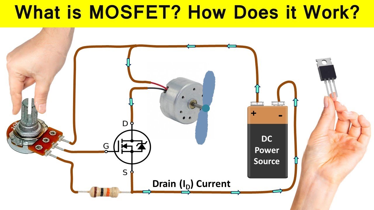
- Connect the motor’s positive side to the 12V supply.
- Connect the motor’s negative side to the MOSFET’s middle pin (the Drain).
- Connect the MOSFET’s rightmost pin (the Source) to the Ground of the 12V supply.
- Connect the Arduino’s Ground to the 12V supply’s Ground. This tripped me up initially, always remember common grounds!
- Connect the MOSFET’s leftmost pin (the Gate) to one of the Arduino’s digital output pins, usually through a small resistor just in case.
I wired it all up. Wrote a simple blink sketch on the Arduino, but instead of blinking the onboard LED, it would just toggle the output pin high and low. High should turn the MOSFET ‘on’, letting current flow through the motor, and low should turn it ‘off’.
Did it Work? Well… Sort Of
Uploaded the code. Nothing. The motor just sat there. I checked my wiring about ten times. Was the motor broken? Nope, connected it straight to 12V, worked fine. Was the MOSFET dead? Maybe. I swapped it for another one. Still nothing.

I started poking around with my multimeter. The Arduino pin was definitely going high (around 5V) and low (0V). The 12V supply was fine. Then I realised my mistake, or rather, my lack of understanding. I’d read somewhere that the Gate needs a certain voltage higher than the Source to turn on properly for an N-channel MOSFET like the IRFZ44N. My Source was connected to ground (0V), and my Gate was getting 5V from the Arduino. That should have been enough.
Turns out, my specific issue was a bit more subtle. I think I had a dodgy connection on the breadboard initially. After reseating everything firmly, then it worked! The motor started spinning when the Arduino pin went high and stopped when it went low. Magic!
Later, I learned about different types, like P-channel for high-side switching, and logic-level MOSFETs that are specifically designed to turn on fully with just 5V or even 3.3V signals, which is often better for microcontrollers. The IRFZ44N technically works, but it’s not always the best choice for direct 5V control, though it did the job for my simple test.
So, yeah, my first real dive into MOSFETs was basically fumbling around until it worked. The key takeaway for me was simple: It really is like a switch. You put a voltage on the Gate, and it connects the Drain and Source pins, letting the main current flow. Remove the Gate voltage, and it disconnects them. Much better than a clunky mechanical relay for simple DC loads, and way more power handling than a basic BJT transistor without needing much current on the control pin. Pretty neat little things, once you get the hang of them.

