Okay, so I was messing around with this MOSFET, trying to get it to switch properly, and I kept running into this issue with the Vgs. You know, the gate-source voltage? It’s kind of a big deal for these things.
First, I grabbed my multimeter and a MOSFET, I think it was an IRF540 or something similar, doesn’t really matter. I just needed something to test with. I also snagged a power supply and some resistors – the usual suspects for a basic circuit setup.
Then I wired up a super simple circuit. You know, power supply to the drain, resistor to limit the current, and the source connected to ground. Nothing fancy, just enough to see if the MOSFET would turn on and off.
The Initial Mess-Up
Initially I connect the gate with out any restrict, then i found my mosfet alway on, So I slapped a resistor between the gate and the power supply, thinking that would do the trick. Nope. The MOSFET was still acting weird, sometimes on, sometimes off, totally unpredictable.
I double-checked all my connections, made sure nothing was shorting out, and even swapped out the MOSFET for another one, just in case I had a dud. Still no luck.
Figuring It Out
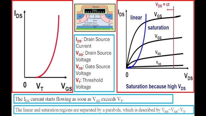
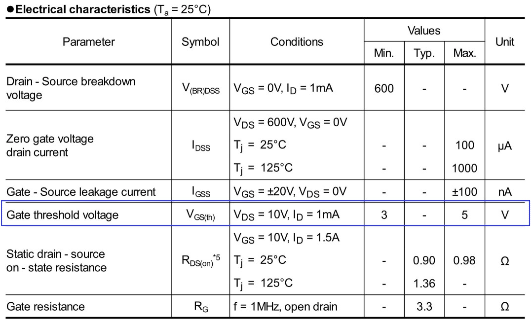
So, I hit the internet, started digging through forums and datasheets. Turns out, the Vgs has a threshold voltage. You gotta get above that voltage to turn the MOSFET on, and below it to turn it off. Makes sense, right?
And there’s this thing called the Miller effect, which I won’t even pretend to fully understand. Basically, it can mess with the gate voltage when the MOSFET is switching, making it harder to control. You’ll need a pull-down resistor to make sure the gate voltage quickly go down to zero
Doing it Right
Here’s what I actually did:
- I added a resistor (around 10k ohms) between the gate and the source. This is called a pull-down resistor. It helps keep the gate voltage at zero when I’m not actively trying to turn the MOSFET on.
- I used another resistor (say, 1k ohms) between the gate and my control signal (which could be from a microcontroller or a simple switch). This limits the current going into the gate.
- I carefully adjusted the control signal voltage, making sure it went above the Vgs threshold to turn the MOSFET on, and below it to turn it off.
And that’s it! Once I had the right resistors in place and was mindful of the Vgs threshold, the MOSFET started behaving exactly as it should. No more weirdness, just clean switching.
It was a bit of a head-scratcher at first, but hey, that’s how you learn, right? By making mistakes and figuring out what went wrong. Now I’ve got a much better handle on how to use these MOSFETs, and hopefully, this little write-up will help someone else avoid the same frustration.