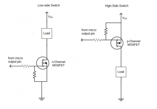
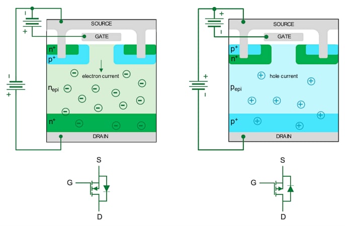
Okay, so today I messed around with P-channel MOSFETs. I’ve used N-channel ones before, but this was my first real dive into the P-channel world. It’s kinda like the opposite, you know?
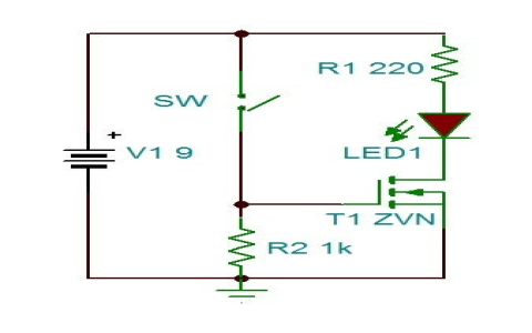
First, I grabbed a breadboard, my trusty power supply, a few resistors (I think 220 ohms and 10k ohms, but don’t quote me), and of course, the P-channel MOSFET itself. I double-checked the pinout online ’cause I always get those mixed up. VDS, VGS…always gotta look it up.
Wiring It Up
The wiring was the trickiest part, honestly. I connected the source pin to the positive rail of my power supply. Then, I took the 10k resistor and put it between the gate and the source. This is your pull-up resistor, super important!
Next, I used the 220-ohm resistor to connect the drain pin to an LED, and then, the LED’s other leg went to the ground. Simple enough, right? It’s a basic circuit just to see this thing in action.
Testing, Testing…
Now, the moment of truth! I turned on the power supply. The LED was ON! Because that pull-up resistor is pulling the gate voltage high, close to the source voltage, which turns the MOSFET OFF. Get it? Opposite of N-channel.
Then, to actually switch the P-channel MOSFET ON, I needed to pull the gate voltage LOW. So, I took a wire and connected it to ground. When I touched the other end of that wire to the gate…BAM! The LED turned off. It worked, because the wire pulled the gate voltage near ground, and it switched ON.
- Connect source to power supply positive.
- 10k resistor between gate and source.
- 220 ohm resistor between drain and LED.
- LED to ground.
- Ground the Gate,Switched ON
I played around with this for a while, just grounding the gate and un-grounding it, watching the LED blink on and off. It’s kind of satisfying, ngl.
So, that’s my little P-MOSFET adventure for the day. It’s not rocket science, but understanding how these things work is pretty fundamental. I will try more about it.