Alright, so I got this project where I needed to figure out the pins on a MOSFET. You know, those little electronic switches that are everywhere in circuits. I’m no expert, but I like to tinker, and I thought I’d share how I went about it.
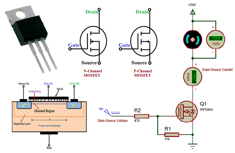
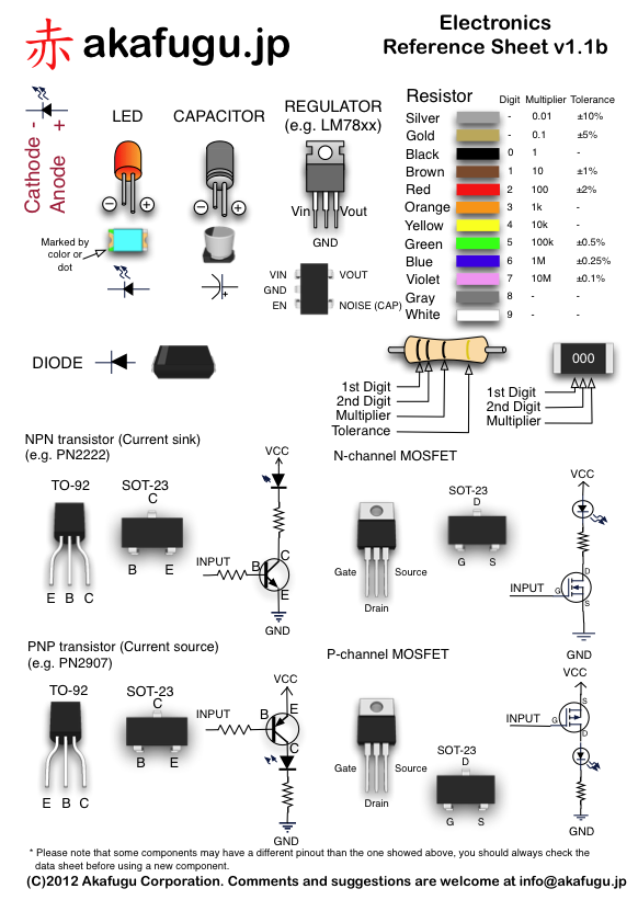
First off, I grabbed the MOSFET I was working with. This particular one was a common N-channel type. You can usually tell it’s an N-channel if it has an arrow pointing away from the gate in the symbol. They come in these little plastic packages with three metal legs sticking out. Those legs are what we care about – they’re the gate, drain, and source.
Now, the tricky part is figuring out which leg is which. I started by looking up the datasheet for the MOSFET. You can usually find this online by searching for the part number printed on the MOSFET itself. The datasheet is like the instruction manual for the component, and it has a diagram showing the pinout.
Finding the Pinout
- Gate (G): This is the control pin. Applying a voltage here turns the MOSFET on or off.
- Drain (D): This is typically where the higher voltage connects.
- Source (S): This is usually connected to the lower voltage or ground.
I found the diagram in the datasheet, and it clearly labeled each pin. Usually, if you hold the MOSFET with the flat side facing you and the legs pointing down, the pins are arranged from left to right as Gate, Drain, and Source. But always double-check the datasheet to be sure!
After I had the pinout from the datasheet, I wanted to test it out. I set up a simple circuit with a battery, a resistor, and an LED. The idea was to use the MOSFET to switch the LED on and off. I connected the positive side of the battery to the drain through the resistor, the source to the negative side of the battery, and the LED between the drain and the positive side of the battery. The gate was connected to a separate small voltage source through another resistor to control the MOSFET.
When I applied a small voltage to the gate, the LED lit up, which means I got it right! The MOSFET was conducting, allowing current to flow from the drain to the source. When I removed the voltage from the gate, the LED turned off. Success! The MOSFET was now blocking the current flow.
It was a pretty cool feeling to see it all work. I mean, it’s a basic thing, but it’s fundamental to how a lot of circuits operate. Plus, it’s always satisfying to learn something new and apply it practically.
So, that’s how I went about figuring out the pins on a MOSFET. It’s a mix of looking up information and doing some hands-on testing. Hope this little walkthrough helps someone out there who’s also curious about how these things work. Just remember to be careful when working with electronics, and always double-check your connections!