Alright so here’s the thing about MOSFETs – I kept seeing these little guys everywhere in circuit diagrams, especially for projects needing serious power control, like switching big motors or handling lots of current. Honestly? I didn’t really grasp how they worked, just kinda copied schematics hoping for the best. That felt pretty dumb, so I decided to actually sit down and figure it out myself, properly this time. No fancy jargon, just hands-on fiddling.
Grabbing Stuff and Just Looking
First things first, I rummaged through my messy parts bin. Found a few different MOSFETs – three common types people mention: n-channel, p-channel, and something called depletion-mode (that one looked old!). They look nearly identical! Tiny black chips with three legs. Just staring at them told me nothing. Needed labels, datasheets? Forget it for now. Time to actually plug them in and see what blows up. Okay, maybe carefully poke them.
Building the Simplest Switch Possible
I grabbed my trusty breadboard, a small LED, a resistor (to protect the poor LED), and a 9V battery. Picked the n-channel MOSFET first. This is where things got slightly confusing:
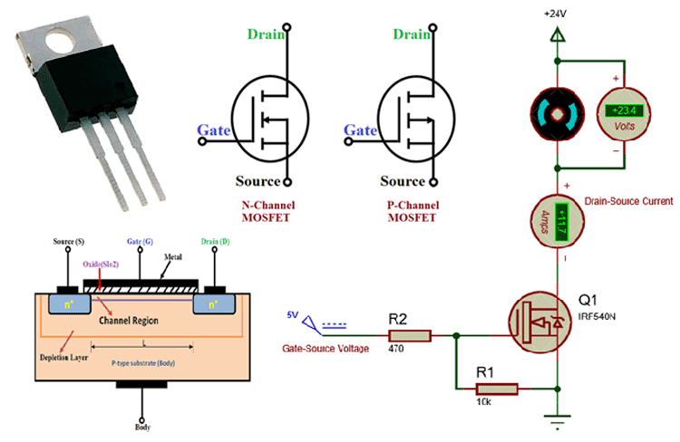
- I figured one leg must be the “in” (Gate), one must be the “out” (Drain), and one connects back to ground (Source). But which leg is which? A quick peek at a random datasheet online (ugh, fine, one tiny bit of research) showed the standard pinout.
- Hooked it up: Battery positive to the LED, then through the resistor to the MOSFET’s Drain leg. LED negative to the Source leg (connected to battery negative/ground). Now the Gate… left it hanging loose. LED did nothing. Dark as night. Expected that.
- Touched a wire from the Gate leg to the battery positive… BAM! LED lit right up. Took the wire off… LED turned off instantly. Okay, cool! So this n-channel guy only lets current flow when I give its Gate leg some positive juice. It’s like a tap I open with voltage. Powerful tap! Used my finger just touching the Gate wire to battery positive and it still worked – super sensitive.
Trying the Other Guys
Okay, n-channel seemed straightforward. What about this p-channel fellow? Same setup: Battery positive to LED and resistor, resistor to Drain… but wait. Different beast.
- Connected LED negative to Source leg… Source leg now connects to battery positive? Felt backwards. Drain connects to battery negative/ground. Yeah, weird.
- LED off when Gate is loose. Touched Gate to ground (battery negative) this time… Pssst, LED flickers weakly. What? Why isn’t it bright? Realized I messed up the Source. For p-channel, Source has to be connected to the positive side. Swapped it: Battery positive straight to Source leg. Drain to the resistor/LED combo, then LED negative to ground. Gate loose – off. Touched Gate to ground… YES! Full brightness. So opposite! Give the Gate less voltage (or ground) to turn it ON. Like a tap that’s normally open and I close it with negative voltage.
- Depletion-mode… honestly, I scratched my head. Couldn’t easily replicate its behaviour with my little battery. It seemed happy letting current flow unless I touched the Gate. Maybe it likes to be “on” by default? Fiddled briefly, it felt less common for my kind of projects, so I set it aside for another day. Focus on the main two.
Why Bother? Real-World Uses Clicked
Playing with the n and p types, it suddenly made sense why you pick one over the other:
- N-Channel: My go-to for most stuff. Why? Because turning it on just needs a positive voltage on the Gate. Super easy to drive directly from things like Arduino pins or most sensors. Powerful, efficient, common. Used one to switch a hefty 12V fan with my tiny microcontroller – felt like magic!
- P-Channel: Trickier to drive since I need to pull its Gate down to ground to turn it on. But super handy in one specific situation: When the load I’m switching is connected directly to the positive rail. Like… switching the entire power supply going into a circuit section. Used one as a simple high-side switch for a motor controller.
The biggest “aha” moment? Realizing MOSFETs are basically voltage-controlled electronic switches. Unlike transistors that need current to flow into the base, the MOSFET’s Gate just sits there, sipping almost no current while letting massive power flow through the other two legs. That makes them incredibly efficient for controlling big stuff with tiny controllers. No more burning out my Arduino pins trying to drive motors directly! Playing with those three tiny legs made the theory finally stick. Now I look at a schematic and actually see the switch, not just a confusing symbol.