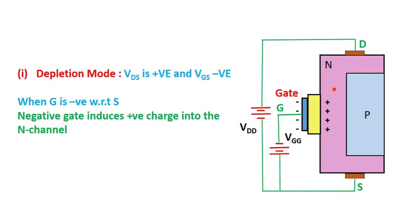
So today I figured I’d actually use these weird depletion mode N-channel MOSFETs that have been sitting in my parts bin forever. You know the ones – most MOSFETs turn on when you apply voltage to the gate, right? These buggers are already on unless you pinch ’em shut. Weird, huh? I never found a real use case for ’em until I dug into some older circuit designs people mentioned online. Here’s what I actually tried building in my cramped little workshop:
Just Grabbing What I Had On Hand
First, I dusted off my ancient DN2540 MOSFETs. Found a basic datasheet online – looked simple enough. Grabbed my breadboard, resistors, jumpers, and the trusty variable bench power supply. Didn’t even bother with a schematic app initially; just scribbled stuff down on a scrap of paper like the old days.
The First Experiment: Constant Current Source
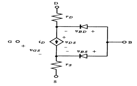
Heard these could make dead-simple current sources. Okay, let’s try. Stuck the MOSFET on the breadboard, source to ground, drain through a resistor to positive. Measured voltage across the resistor… nothing. Right, depletion mode remembers? Had to flip things. Tied the gate down to ground. Boom! Suddenly getting steady current flowing! Literally just two parts: The MOSFET and a resistor. Blew my mind. Set the current by changing the resistor value. Super basic power for LEDs maybe? Wrote that down.
Then I Tried That Weird ‘Normally On Switch’ Thing
Okay, so it stays on unless you turn it off. Built the simplest switch circuit: Source to ground, load between drain and positive supply. Left the gate floating? Load stayed on. Powered the load? On. Blew my nose? Still on. Hooked the gate to ground? Bingo, switched right off. Mind clicked: This could actually be useful for safety stuff where you want the circuit running if something fails open. Like a sensor fails, gate floats, switch stays ON. Safety-critical lights, maybe? Marked that as #2.
High-Voltage Regulator? Yeah, Sorta…
People talked about using these for simple high-voltage regulation. Tried making a zener-less follower. Used a voltage divider to set the gate voltage lower than the output I wanted at the source. Load hooked up to source. Fed it maybe 40V? Source voltage sat rock solid at whatever the divider set minus a bit. Not super tight regulation, but darn cheap if you just need something “around there” with high voltage input. Wrote: “Sloppy But Functional H.V. Reg.” as #3.
The Unexpected Reversal: AC Signal Clip
Pure accident. Had an audio signal generator running while messing. Connected gate to ground, source to signal. Measured the drain through a load resistor to V+. Whoa! Noticed it clipped the signal nicely only when the AC went negative. Dug deeper. Turns out, tying gate to ground sets the threshold. When the source swings negative below that… conduction changes sharply. Instant asymmetric clipper circuit for protecting inputs? Jotted that as surprise find #4.

Last Shot: Simple Active Load
Remember that constant current thing? Thought, maybe stick it in an amplifier stage instead of a boring resistor. Replaced the drain resistor in a basic amp setup with my depletion MOSFET current source setup. Measured the gain. Actually higher than with the resistor! The super high impedance of the MOSFET helps. Nice way to boost simple amp gain without complex circuitry. Perfect for that weird hobby project needing a bit more oomph. Filed that under #5.
Honestly, these components gave me a nasty surprise first because I fought how they worked instinctively. But once I got my head around them being “normally on”, a bunch of simple, niche uses popped up. Won’t replace regular MOSFETs in most stuff, but for specific jobs where you need stuff on by default, constant current on the cheap, or handling silly high voltages easily? Yeah, they earned their spot back in my drawers. Just label them clearly this time!