My Confusion Before Starting
So look, I kept getting totally mixed up between these “Common Drain” and “Source Follower” things people talk about with MOSFETs. Every time I saw one mentioned online, I’d get this sinking feeling. Like, which one is which? And why should I even care?
Honestly, I just wanted someone to explain it like I’m kinda dumb. So screw it, I figured I’d just mess around on my bench myself and see what the heck actually happens.
Grabbing My Stuff & Setting Up
Right then, I cleared off my messy workbench – found my trusty breadboard under a pile of loose resistors. Dug out one of those N-channel MOSFETs, the common little ones. Grabbed a power supply, my function generator that makes wavy signals, my scope to see stuff, a bunch of resistors and jump wires. Felt good having everything laid out ready to poke.
Throwing the Common Drain Together
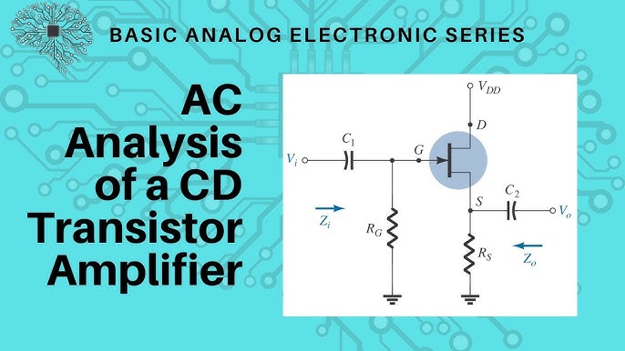
Okay, first shot. Went with this setup:
- Stuck the MOSFET onto the breadboard.
- Plugged the Gate wire straight into the wavy signal from my generator.
- Took the Source pin, connected it down to Ground BUT through a resistor first.
- Drain pin? Linked that directly to my power supply’s positive. Keep it simple.
- Then I hooked my scope probe to the Source pin. Needed to see what came OUT.
Flipped everything on. The scope showed… kinda weird. The wave coming OUT from the Source looked just like the wave I put IN at the Gate! But hang on… it looked weaker. Like, if I shoved in 5 volts peak-to-peak, maybe only 4.5 volts came out? And it felt slower somehow too? That was strange.
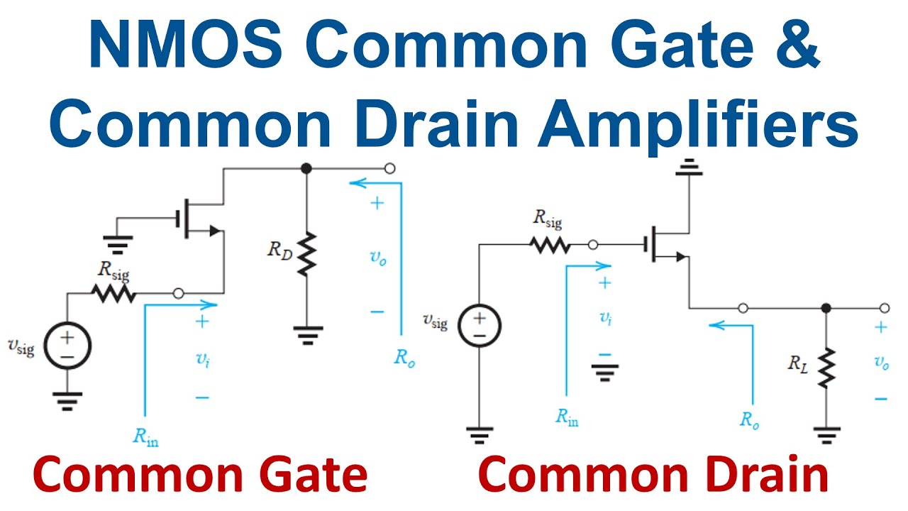
So basically, output comes from the Source, drain tied straight to power, gate gets the input. They call that one Common Drain. I scribbled notes: “Copies Gate input but sucks a bit? Weaker & laggy?”
Switching to Source Follower Mode
Now I’m thinking, “But dude, I’ve heard ‘Source Follower’ too!” Felt like deja vu. Was this different? I changed things up.
- Gate still got my input signal generator.
- Source still went to Ground through a resistor.
- Drain STILL hooked directly to the power supply.
Uhh… wait a minute. Looking at my notes, THIS WAS THE SAME EXACT CIRCUIT AS BEFORE! I sat there blinking. Then it hit me. Oh. My. God. These fancy names… they’re literally talking about the exact same circuit connection! “Common Drain” just means the Drain pin is shared, connected to that fixed power supply voltage. “Source Follower” just tells you the output is taken from the Source, and guess what? That output tries to “follow” whatever voltage you put on the Gate. Just… different ways of describing the exact same physical setup on my breadboard.
I felt kinda dumb. All that time confused, and it was just one thing! What a waste of brainpower.
What Actually Makes It Tick
Even though it’s one circuit, playing with it showed me some cool stuff:
- It NEVER makes the signal bigger (no amplification gain). In fact, the output wave is always a bit weaker than the input wave. That little voltage drop is annoying.
- But the killer thing? It barely puts any “pull” on whatever is feeding the input! Super light touch on the source side. Super strong drive on the output side.
- So it’s like a good buddy – buffers the signal. Protects your input device from needing to push hard, while giving your output device a strong kick.
So Why Bother Knowing Both Names?
Well, turns out this is mostly pointless confusion. “Common Drain” just focuses on how the circuit connects (Drain fixed to supply voltage). “Source Follower” focuses on what the circuit actually does (output follows input from Source). Two sides of the exact same coin sitting right there on my bench.
My Takeaway After All That
This little adventure saved me. Now when I see schematics or people talking:
- See Drain tied straight to V+ or Vdd? Ding ding! That’s your Common Drain / Source Follower circuit. Doesn’t matter which name they use.
- Remember it’s a buffer – protects your input, drives your output hard, but weakens the signal slightly. That’s the core job.
Forget memorizing complex definitions. The connection tells you the story. Feeling way less stressed about circuits now!