Alright folks, settle in, let me tell you how I wrestled with my Arduino trying to control bigger lights the other day. My plan was simple: turn some powerful lamps on and off using just a tiny Arduino pin. Yeah, ambitious for a tiny board.
The ‘Let’s Just Try This’ Phase
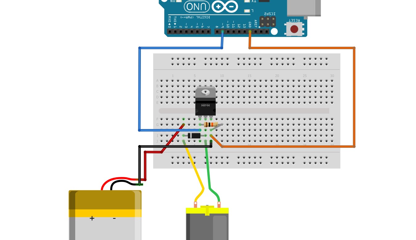
First thought? “Oh, I’ll just plug a transistor directly!” Grabbed one of those little signal transistors I had lying around. Hooked it up quick and dirty: Arduino pin straight to the transistor’s base, the lamp between the collector and a power source, emitter to ground. Fired up the basic blink sketch. BAM! Lamp lit up! Felt pretty smug for about two seconds.
Then… I noticed the lamp was dim. Like, seriously dim. Tried to power a brighter lamp? Nada. Nothing. Zip. The poor Arduino pin looked miserable, and the transistor got way too hot to touch. Realized I was basically trying to lift a truck with a hamster wheel – totally overloaded. Fried my first transistor trying to push too much juice. Lesson learned the hot, smoky way: regular transistors aren’t built for this heavy lifting.
The ‘Time to Bring In the Big Gun’ Phase
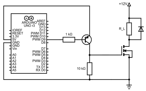
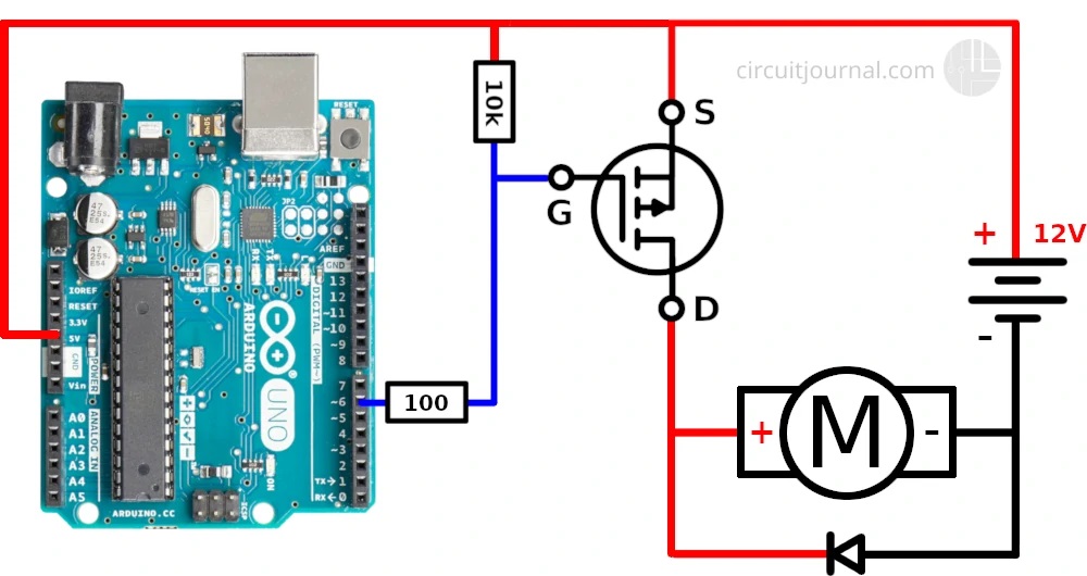
Scratching my head, I remembered something about these things called MOSFETs. Supposedly they’re awesome for controlling big power with tiny signals. Dug through my messy electronics box and found an IRF520 MOSFET. It looked sturdy. Did some quick googling to remind myself which leg was which – gate, drain, source. Gate is like the control knob.
Time to rewire:
- Arduino Pin 9 got soldered to a 220 Ohm resistor. Why? Because I blew stuff up earlier, adding a safety resistor seemed wise.
- Resistor other end went straight to the MOSFET’s Gate leg.
- MOSFET Source leg went straight to Ground (negative side of my separate power for the lamp).
- Power for Lamp positive went to one leg of my powerful lamp.
- Lamp’s other leg got connected to the MOSFET’s Drain leg. So all the lamp current has to flow through the MOSFET.
- My hefty power supply (12V, beefy amp rating) connected negative to the same Ground, positive to the lamp.
- Key step! Connected the Ground from my Arduino to the Ground of the big lamp power supply. Absolutely cannot skip this!
Looked like a bird’s nest, but I figured it might work.
The ‘Why Isn’t This Working?!’ Phase
Uploaded a simple blink sketch again. Crickets. Lamp did nothing. Checked wiring three times. Pulled my hair out a little. Measured voltage at the Gate: blinked fine with the Arduino, about 5V on/off. Okay, signal was getting there.
Then I remembered: some MOSFETs won’t turn on fully with only 5V. Mine might be one! Needed more voltage on the Gate. Problem: Arduino only gives 5V.
Time to get creative:
- Swapped the resistor connecting Arduino pin to Gate to a higher value? Nope, worse.
- Tried different Arduino pins? Same result. Sad lamp.
- Wondered if my MOSFET was fried too? Sigh.
Finally, after some more frantic searching, I saw people mention Logic-Level MOSFETs. These are specifically designed to work happily with the 5V from microcontrollers like Arduino.
Dug through my box again. Found a different MOSFET labeled IRLZ44N. Supposedly this one was a logic-level type. Desperate times! Yanked out the IRF520, popped in the IRLZ44N using the exact same wiring.
The Sweet Success Phase
Uploaded the blink sketch. Held my breath…
BLINK! The lamp clicked on fully! Bright! Then off! On! Off! Like a beautiful, high-power lighthouse! The MOSFET stayed cool to the touch! Victory dance commenced!
So, the messy takeaway:
- Regular transistors? Nope for big power control.
- Regular MOSFETs? Sometimes nope with 5V Arduino unless designed for it.
- Logic-Level MOSFETs like IRLZ44N? YES! Play nice with Arduino.
- Don’t forget the Ground connection between Arduino and your big power supply! It links the systems.
- A small resistor on the Gate? Probably smart to protect the Arduino pin.
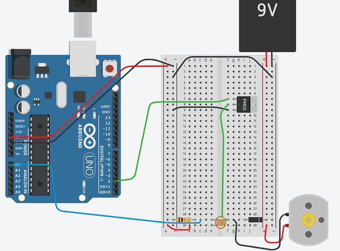
My bench is a disaster, but I got it working. Saved me buying pre-made modules, felt good figuring it out. Now onto controlling motors… wish me luck!